
An Assembly Clearance Monitoring System for Shaft Hole Components

A technology for component assembly and monitoring system, applied in measurement devices, optical devices, instruments, etc., can solve the problems of difficult assembly monitoring, low efficiency, large manual monitoring errors, etc., to facilitate visualization, improve adjustment efficiency, and reduce measurement. effect of error

Active Publication Date: 2019-05-28
HUBEI SANJIANG AEROSPACE GRP HONGYANG ELECTROMECHANICAL
View PDF8 Cites 0 Cited by
  • Summary
  • Abstract
  • Description
  • Claims
  • Application Information

AI Technical Summary

Problems solved by technology

[0005] The invention provides a monitoring system for the assembly clearance of shaft-hole parts, which solves the technical problems of large-scale shaft-hole parts assembly monitoring difficulty, large manual monitoring error and low efficiency in the prior art

Method used


Image

  • An Assembly Clearance Monitoring System for Shaft Hole Components

Examples


Embodiment Construction

[0035] The embodiment of the present application provides a solution to the assembly gap monitoring system of shaft and hole parts in the prior art, and solves the technical problems of large-scale shaft and hole parts assembly difficulty, large manual monitoring error and low efficiency in the prior art.

[0036] In order to better understand the above technical solutions, the above technical solutions will be described in detail below in conjunction with the accompanying drawings and specific implementation methods. It should be understood that the embodiments of the present invention and the specific features in the embodiments are detailed descriptions of the technical solutions of the present application. , rather than limiting the technical solutions of the present application, the embodiments of the present application and the technical features in the embodiments can be combined without conflict.

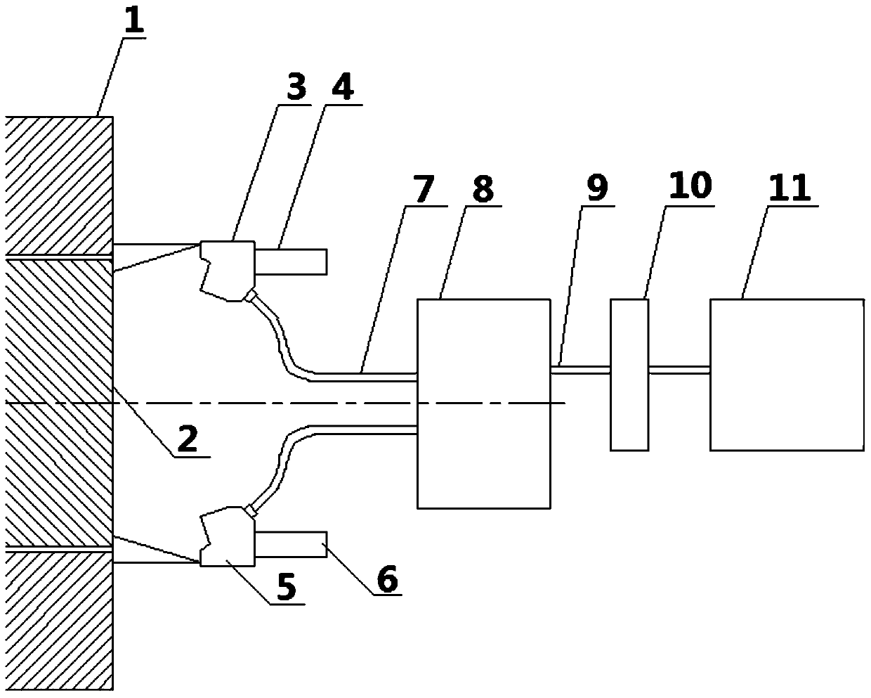
[0037] see figure 1 , an assembly gap monitoring system for shaft and h...


PUM


Abstract

The invention belongs to the technical field of assembly of large-scale shaft-hole parts, and discloses a monitoring system for the assembly clearance of shaft-hole parts, including: a laser measuring head, a contour measuring controller and a display terminal; the laser measuring head is connected to the contour measuring instrument The profile measuring instrument is connected to the display terminal; wherein, when performing the measurement, the laser measuring head emits diffused laser light to the shaft hole, monitors the change of the shaft hole gap, and sends it back to the profile measuring instrument in real time, and further displayed on the display terminal. The invention provides an efficient and highly reliable monitoring system.

Description

technical field [0001] The invention relates to the technical field of assembly of large shaft hole parts, in particular to a monitoring system for the assembly gap of shaft hole parts. Background technique [0002] Large-scale shaft-hole parts are the core components of some large-scale electromechanical equipment, and the assembly requirements of shaft-hole parts of some electromechanical equipment are relatively high. [0003] Especially in large-scale electromechanical equipment, due to the large size and heavy weight of the shaft-hole parts, and the small gap between the shaft and the shaft hole, contact, collision, scratching, etc. are not allowed between the shaft and the shaft hole during the assembly process. damage. [0004] The monitoring of the assembly gap between the shaft and the shaft hole parts of the existing large-scale electromechanical equipment is completed through manual visual inspection of the gap; thus it is difficult to adjust the assembly between...

Claims


Application Information

Patent Timeline
Patent Type & Authority Patents(China)
IPC IPC(8): G01B11/14G01B11/24
CPCG01B11/14G01B11/24
Inventor 汤浩罗宏毅刘新明
Owner HUBEI SANJIANG AEROSPACE GRP HONGYANG ELECTROMECHANICAL
Learn More