Propeller thrust measuring device

A technology of measuring devices and propellers, which is applied in the direction of measuring devices, outboard propulsion devices, propulsion device engines, etc., can solve the problems of insufficient balance integration, time-consuming and laborious, and inaccurate data, and achieve high practical value, accurate measurement, and structural simple effect

Active Publication Date: 2016-10-12
HARBIN ENG UNIV
View PDF6 Cites 21 Cited by
  • Summary
  • Abstract
  • Description
  • Claims
  • Application Information

AI Technical Summary

Problems solved by technology

[0005] First of all, the equipment is too bulky and unintelligent. After fixing the propeller on the test equipment, it takes a lot of manual work to move the test equipment to the vicinity of the circulating water tank and buckle it upside down in the water tank. Sometimes a crane is used to lift the test equipment
[0006] Secondly, for the same propeller, only the thrust data in the forward direction is not enough, so after the propeller forward test is completed, the equipment must be reversed. The above test process is not only time-consuming and laborious, but may also cause injury to the test personnel
[0007] Finally, today's test equipment and balances are not integrated enough, and the balance is delicate and easy to damage. During the test, the data transmission lines of the balance are always exposed, and these wires are generally relatively thin. The test failed; in addition, the current in the data transmission line is milliamp level, and the current of the propeller motor can reach the level of ampere. The large current has strong interference with the small current, and the influence between the two will cause the data measured in the test to be inaccurate. Severe damage to the instrument

Method used


Image

  • Propeller thrust measuring device
  • Propeller thrust measuring device
  • Propeller thrust measuring device

Examples


Embodiment Construction

[0018] The present invention will be further described in detail below in conjunction with the accompanying drawings and specific embodiments.

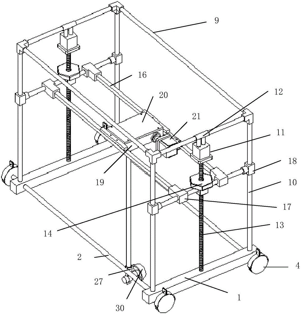
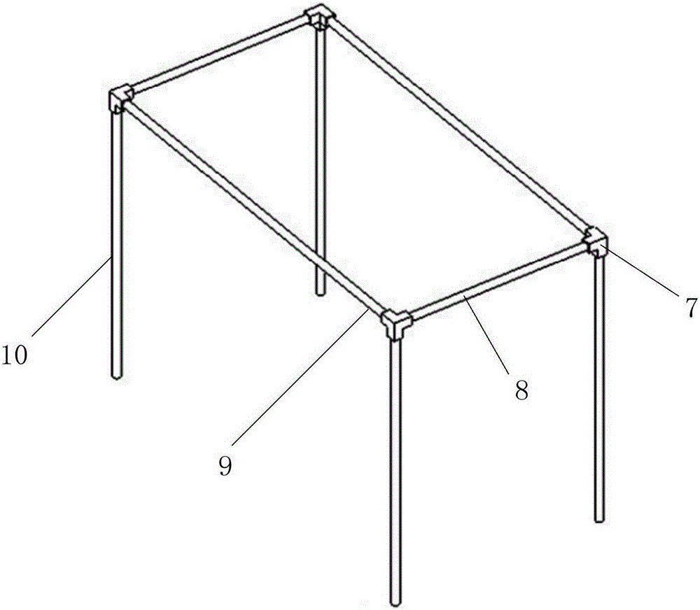
[0019] combine Figure 1 to Figure 7 , the present invention includes a base, an upper frame, two screw systems, a worm gear system and a measuring system. Sliding on the rod, the worm system and the measuring system are fixed on the screw system to control the rotation.

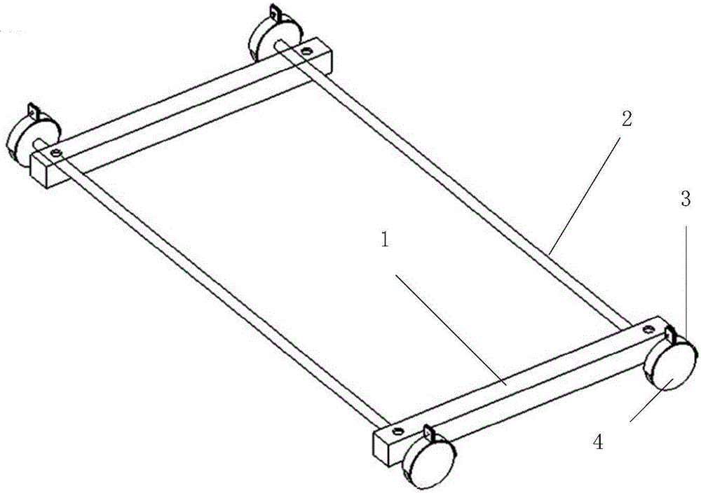
[0020] The base is composed of two support rods 1, two shafts 2, a locking device 3 and four bearing wheels 4. The structure is similar to the chassis part of a four-wheeled automobile. The four load-bearing wheels are divided into two groups, which are respectively connected to the shafts. The two groups are arranged symmetrically. Both shafts pass through the bracket and can rotate freely in the bracket. figure 2 shown. Fastening devices such as image 3 As shown, it consists of locking device 3, locking device 5 and locking screw 6. The load-bearing wheels ...


PUM


Abstract

The invention provides a propeller thrust measuring device, which comprises a base, an upper part frame, two lead screw systems, a worm gear and worm system, and a measuring system. The entire propeller thrust measuring device spans over a circulating water tank, and the center line of the device and that of the circulating water tank are on the same vertical plane; a lifting column is lowered to an appropriate depth by utilizing the lead screw systems after a propeller and a balance are fixed, and the lifting column is rotated via the worm gear and worm system so as to adjust an axis of the propeller to be coincide with the center line of the circulating water tank; and the propeller is turned on to a certain rotation speed, the balance can transmit a thrust value of the propeller to a water surface data acquisition instrument under the condition of zero flow velocity, and a thrust value of the propeller under the condition of a flow velocity can be measured through turning on a flow generating device of the circulating water tank. The propeller thrust measuring device is simple in structure, accurate in measurement and high in practical value, can provide important reference numerical values for propeller thrust measurement of water surface and underwater vehicles, and can conduct motion control research of the vehicles more precisely.

Description

technical field [0001] The invention relates to a measuring device, in particular to a propeller thrust measuring device, which is applied in a circulating water tank to measure propeller thrust, and belongs to the field of aircraft propeller thrust measurement. Background technique [0002] With the depletion of land resources, human beings have turned their attention to the rich marine resources. In addition to ships sailing on the sea, a variety of marine detection equipment has emerged, such as HOV, ROV, UUV, AUV, etc. These equipment are excellent The shortcomings are obvious and there are many differences, but the vast majority of marine exploration equipment uses propellers as propulsion equipment. To sum up, accurate measurement of various parameters of the propeller is of great significance to the overall design, dynamic analysis and even motion control of the aircraft. [0003] According to the knowledge of the ship principle, the open water test of the propeller ...

Claims


Application Information

Patent Timeline
Patent Type & Authority Applications(China)
IPC IPC(8): G01L5/13B63H20/36G01M10/00
CPCB63H20/36G01L5/133G01M10/00
Inventor 李晔郭宏达曹建龚昊姜言清王汝鹏马腾雷明安力何佳雨
Owner HARBIN ENG UNIV
Why Eureka
Try Eureka