Optical anti-shake day-and-light switcher module set technique capable of increasing production yield
An optical anti-shake, switcher technology, applied in optics, optical components, instruments, etc., can solve the problems of high product defect rate and complex assembly process steps, avoid complex process steps, improve product yield, process reasonable effect
- Summary
- Abstract
- Description
- Claims
- Application Information
AI Technical Summary
Problems solved by technology
Method used
Image

Examples
Embodiment 1
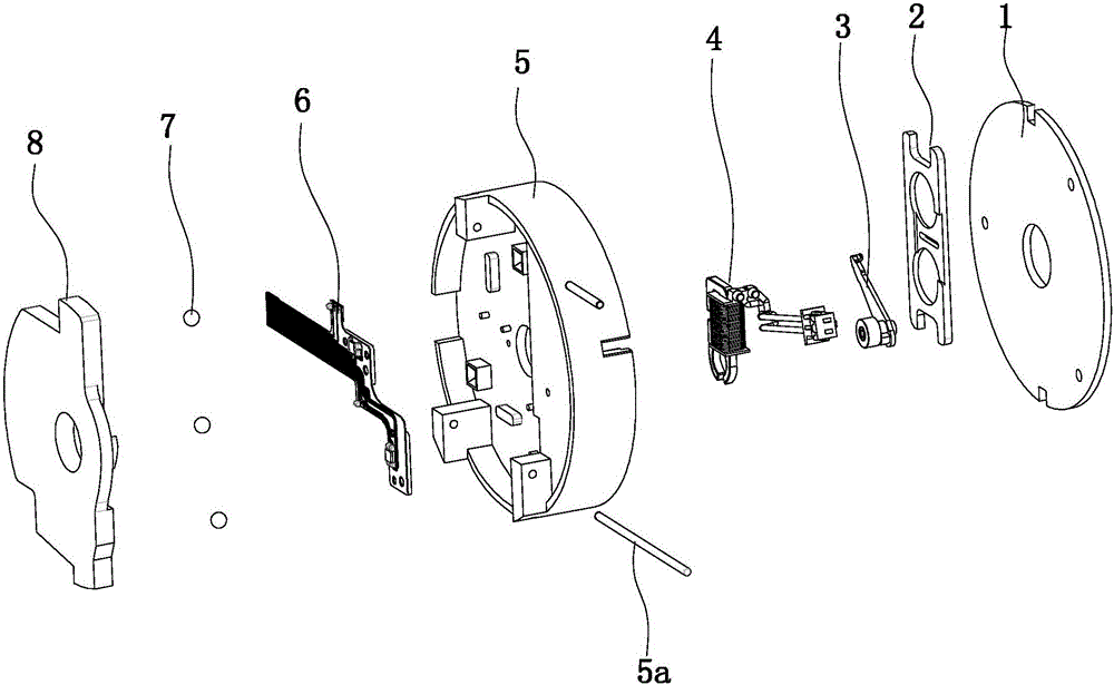
[0055] Embodiment 1: as figure 1 As shown, an optical anti-shake day and night switcher module process that improves production yield includes solenoid valve body engineering, assembly assembly engineering, magnet rocker assembly engineering, skateboard magnetic block assembly engineering, and FPC assembly engineering (FPC refers to flexible circuit board), fixed seat assembly engineering and module assembly engineering. The optical anti-shake day and night switcher module of this embodiment includes a fixed cover 1, a solenoid valve body 4, an assembly part 2, a magnet rocker assembly 3, a fixed seat assembly 5, a positioning rod 5a, an FPC assembly 6, a ball 7 and a slider magnet. Block component8.
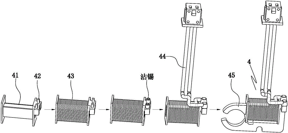
[0056] Such as figure 2As shown, the solenoid valve body project includes a bobbin 41, an external wire 44 and a U iron 45. Two connecting posts 42 are arranged on the bobbin. The breakout wire has two conductors. The assembly process of the solenoid valve body project inc...
Embodiment 2
[0075] Embodiment 2, all the other structures and processes of this embodiment are with reference to embodiment 1, and its difference is:
[0076] The assembly process of the assembly project of the assembly component includes the following steps in sequence:
[0077] A, frosting the bottom surface and sides of the glass sheet installation groove;
[0078] B, Dispensing glue on the bottom surface of the glass sheet installation groove;
[0079] C. Paste the glass piece in the glass piece installation groove.
Embodiment 3
[0080] Embodiment 3, all the other structures and processes of this embodiment are with reference to embodiment 1, and its difference is:
[0081] Such as Figure 9 , Figure 10 , Figure 11 As shown, the assembly project of the assembly also includes the assembly tooling of the assembly. Assembling upright parts assembly tooling comprises frame, is arranged on the installation plate 96 on the frame, is arranged on the vertical guide sleeve 91 below the installation plate, is slidably arranged on the vertical guide rod 93 in the vertical guide sleeve, is arranged on the vertical The movable stopper 95 on the top of the guide rod and corresponding to the light-transmitting window. The cross-section of the movable block corresponds to the light-transmitting window. A limiting block 94 is arranged on the outer surface of the movable block. The mounting plate is provided with an opening for a movable stopper to give way. The movable stopper passes through the relief opening ...
PUM
 Abstract
Description
Claims
Application Information
PatSnap Eureka turns technology decisions into work you can execute. Powered by our Innovation Knowledge Graph, it runs expert workflows across engineering, life sciences, materials and intellectual property. Get your review-ready output in minutes.


