
Beat-type electromagnetic relay used for high-voltage direct current

An electromagnetic relay, high-voltage direct current technology, applied in the direction of electromagnetic relay, electromagnetic relay details, relays, etc., can solve the problems of complex high-voltage direct current relay process, inability to ensure stable contact of contacts, failure to meet insulation requirements, etc., to achieve simple structure, Increased pressure, well-designed effects

Active Publication Date: 2016-10-12
HUIZHOU EVE TECH CO LTD
View PDF12 Cites 4 Cited by
  • Summary
  • Abstract
  • Description
  • Claims
  • Application Information

AI Technical Summary

Problems solved by technology

Because the air gap distance between the armature and the iron core is very short, in the high-voltage field, this traditional snap-fit ​​electromagnetic relay cannot meet the insulation requirements and is easily broken down
[0003] In the existing snap-on electromagnetic relay, whether it is a single-break point or double-break point contact structure, when the circuit is connected, there is a huge electric repulsion between the two contacts to force the contacts to bounce back, and the arc is accompanied by occurs, making contact ablation serious
Especially in the case of extremely high current, the pressure between the contacts cannot guarantee the stable contact of the contacts, and the contacts are switched repeatedly in the open and closed states, the relay will burn out quickly, and there is a great risk of explosion
[0004] The existing high-voltage DC relay adopts a solenoid structure, and the contacts are placed in a sealed environment, which is vacuum or high-pressure gas, which is class I pollution, and can achieve high voltage and large Current switching, but this high-voltage DC relay process is complex and expensive

Method used


Image

  • Beat-type electromagnetic relay used for high-voltage direct current
  • Beat-type electromagnetic relay used for high-voltage direct current
  • Beat-type electromagnetic relay used for high-voltage direct current

Examples


Embodiment Construction

[0026] In order to facilitate the understanding of the present invention, the present invention will be described more fully below with reference to the associated drawings. Preferred embodiments of the invention are shown in the accompanying drawings. However, the present invention can be embodied in many different forms and is not limited to the embodiments described herein. On the contrary, the purpose of providing these embodiments is to make the disclosure of the present invention more thorough and comprehensive.

[0027] It should be noted that when an element is referred to as being “fixed” to another element, it can be directly on the other element or there can also be an intervening element. When an element is referred to as being "connected to" another element, it can be directly connected to the other element or intervening elements may also be present. The terms "vertical," "horizontal," "left," "right," and similar expressions are used herein for purposes of ill...


PUM


Abstract

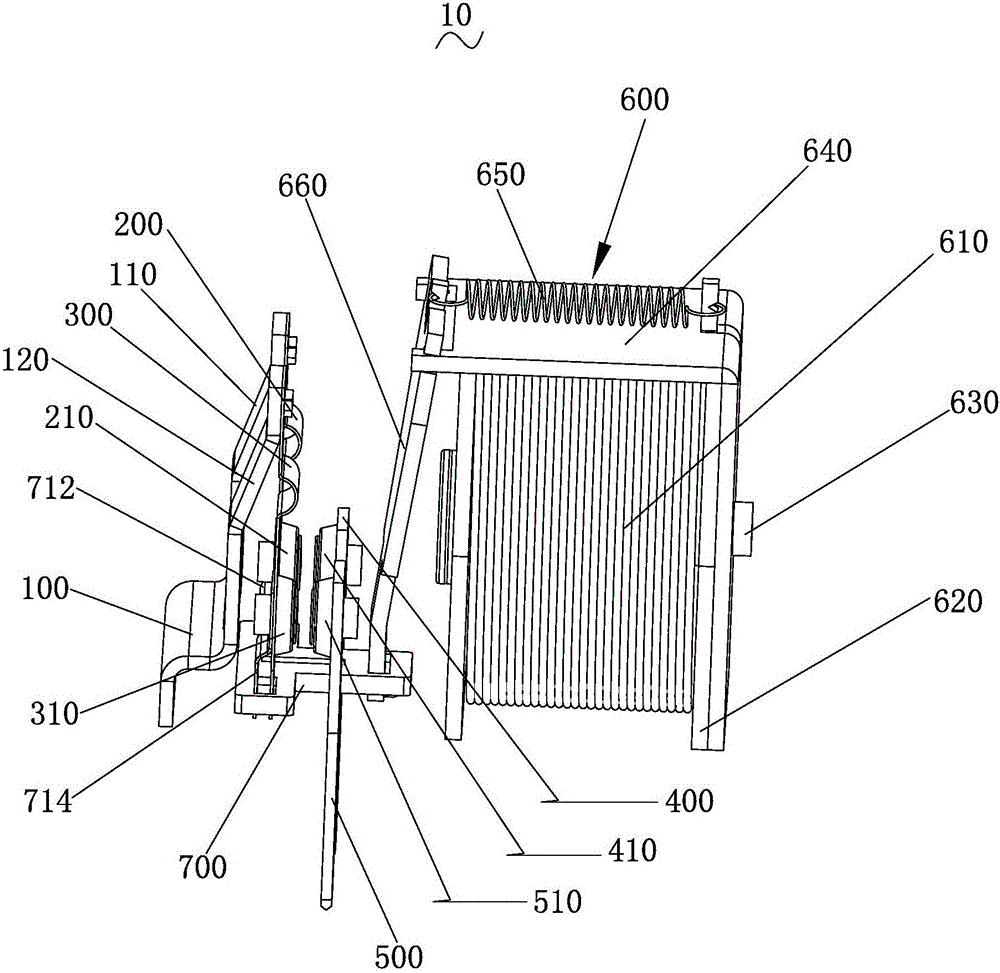
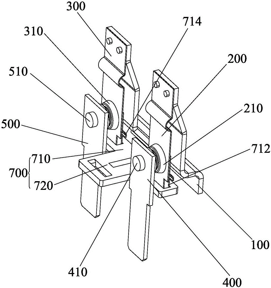
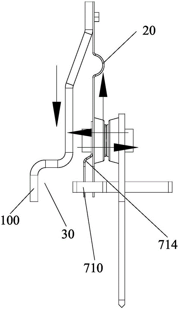
The invention discloses a beat-type electromagnetic relay used for high-voltage direct current. The beat-type electromagnetic relay comprises a connecting plate, a first movable spring plate, a second movable spring plate, a first static conducting plate, a second static conducting plate, a beat-type drive assembly and a pushing plate. The connecting plate is provided with a first conducting plate and a second conducting plate, each of the first movable spring plate and the second movable spring plate is provided with a fixed end and a free end, the fixed end of the first movable spring plate is fixed onto the first conducting plate, the free end of the first movable spring plate is connected with the pushing plate, the fixed end of the second movable spring plate is fixed onto the second conducting plate, and the free end of the second movable spring plate is connected with the pushing plate; the pushing plate is used for driving the free end of the first movable spring plate and the free end of the second movable spring plate to be connected or disconnected with the first static conducting plate and the second static conducting plate respectively; and the beat-type drive assembly is used for driving the pushing plate to perform a reciprocating motion. The beat-type electromagnetic relay used for high-voltage direct current disclosed by the invention has the advantages of simple structure, low price, cost reduction and the like.

Description

technical field [0001] The invention relates to the technical field of relays, in particular to a snap-in electromagnetic relay for high-voltage direct current. Background technique [0002] In the existing snap-on electromagnetic relay, the moving reed and the armature are connected by riveting, and the two are connected by metal to metal, and the moving reed moves with the armature. Because the air gap distance between the armature and the iron core is very short, in the high-voltage field, this traditional snap-fit ​​electromagnetic relay cannot meet the insulation requirements and is easily broken down. [0003] In the existing snap-on electromagnetic relay, whether it is a single-break point or double-break point contact structure, when the circuit is connected, there is a huge electric repulsion between the two contacts to force the contacts to bounce back, and the arc is accompanied by Occurs, causing serious contact ablation. Especially in the case of extremely hig...

Claims


Application Information

Patent Timeline
Patent Type & Authority Applications(China)
IPC IPC(8): H01H50/24H01H1/50
CPCH01H1/50H01H50/24
Inventor 罗楠李开波刘金成
Owner HUIZHOU EVE TECH CO LTD
Learn More