Multi-directional near-field communication antenna device
A near-field communication antenna and antenna device technology, which is applied in the direction of antenna support/installation device, loop antenna with ferromagnetic material core, radiation element structure, etc., can solve the problem of single radiation direction of near-field antenna, and achieve The effect of improving the reading and writing distance
- Summary
- Abstract
- Description
- Claims
- Application Information
AI Technical Summary
Problems solved by technology
Method used
Image

Examples
Embodiment 1
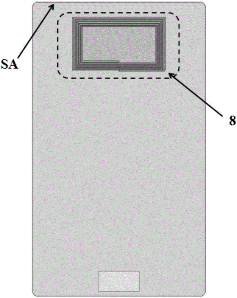
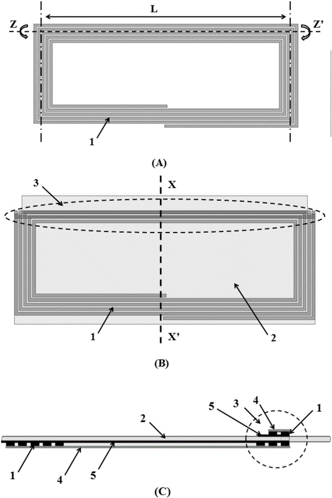
[0028] Such as image 3 As shown, a planar quadrilateral helical antenna with an area of 40mm×20mm is made, designed with 5 turns, the line width is 0.4mm, and the line spacing is 0.2mm. Fold the gap in half, and make a hole along the gap, and pass the magnetic material through the hole, that is, the quadrilateral helical antenna sandwiches the magnetic material layer in the middle, the thickness of the magnetic material layer is 0.1mm, and the real part of the magnetic permeability of the magnetic material is 150@13.56 MHz, the imaginary part of magnetic permeability 2@13.56MHz, the antenna is assembled on the inner surface of the mobile electronic device near the top, which is recorded as the antenna device of the present invention.
[0029] Make a planar quadrilateral helical antenna with an area of 40mm×20mm, adopt 5-turn design, line width 0.4mm, line spacing 0.2mm, lay a magnetic material layer on the bottom, the thickness of the magnetic material layer is 0.1mm, and...
Embodiment 2
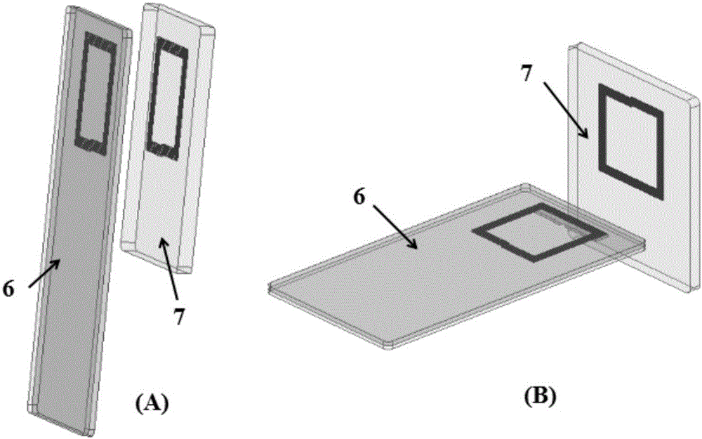
[0034] Such as image 3 As shown, make a planar quadrilateral helical antenna with an area of 40mm×10mm, adopt 5-turn design, line width 0.5mm, line spacing 0.2mm, fold in half along the gap between the second and third wires on the longer side of the quadrilateral helical antenna , and make a hole along the gap, and pass the magnetic material through the hole, that is, the quadrilateral helical antenna sandwiches the magnetic material layer in the middle, the magnetic material area is 40mm×12mm, the magnetic material layer thickness is 0.2mm, and the magnetic permeability of the magnetic material is The real part is 150@13.56MHz, and the imaginary part of the magnetic permeability is 2@13.56MHz. The antenna is mounted on the side wall of the mobile electronic device, such as Figure 5 As shown, the antenna device of the present invention is formed.
[0035] Make a planar quadrilateral helical antenna with an area of 40mm×10mm, adopt a 5-turn design, a line width of 0.5mm...
PUM
| Property | Measurement | Unit |
|---|---|---|
| Thickness | aaaaa | aaaaa |
| Permeability | aaaaa | aaaaa |
| Permeability | aaaaa | aaaaa |
Abstract
Description
Claims
Application Information
 - R&D
- Intellectual Property
- Life Sciences
- Materials
- Tech Scout
- Unparalleled Data Quality
- Higher Quality Content
- 60% Fewer Hallucinations
Browse by: Latest US Patents, China's latest patents, Technical Efficacy Thesaurus, Application Domain, Technology Topic, Popular Technical Reports.
© 2025 PatSnap. All rights reserved.Legal|Privacy policy|Modern Slavery Act Transparency Statement|Sitemap|About US| Contact US: help@patsnap.com