
Vehicle collision alarming and recording triggering device and detection method thereof

A technology of collision alarm and recording device, applied in the field of intelligent car networking, can solve the problems of easy interference from surrounding noise, inability to accurately determine the location of the sound source, misjudgment, etc., to achieve the effect of convenient alarm and proof

Active Publication Date: 2016-10-12
BEIJING TAIFANG TECH CO LTD
View PDF14 Cites 16 Cited by
  • Summary
  • Abstract
  • Description
  • Claims
  • Application Information

AI Technical Summary

Problems solved by technology

The disadvantage of the above-mentioned prior art is that it is impossible to accurately determine the location of the sound source, and surrounding noises (such as sirens, voices, and various audio sounds) are prone to interference, resulting in misjudgments and missed judgments.

Method used


Image

  • Vehicle collision alarming and recording triggering device and detection method thereof
  • Vehicle collision alarming and recording triggering device and detection method thereof
  • Vehicle collision alarming and recording triggering device and detection method thereof

Examples


Embodiment 1

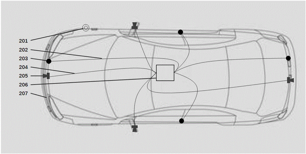
[0032] The invention proposes a triggering collision alarm and recording device, specifically, the triggering collision alarm and recording device can be applied in the field of automobiles. See attached figure 1 As shown, the sensors 203 for collecting collision signals are respectively installed on the four main surfaces of the car shell 207 . In the present invention, the sensors may include but not limited to piezoelectric ceramics or piezoelectric thin films based on piezoelectric effects, sensor devices based on acoustoelectric effects such as microphone arrays and MEMS systems thereof. The sensors 203 are respectively connected to the central processing unit 206 through sensor connection lines 202 . In this embodiment, four image acquisition devices 205, such as cameras, are respectively installed near the center of the front and back on the car shell 207 and on the left and right rearview mirrors. The image acquisition device 205 is respectively connected to the cent...

Embodiment 2

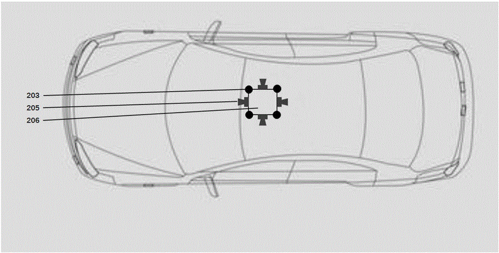
[0041] See attached figure 2 As shown, in the structural installation diagram of this embodiment, the sensor 203 and the image acquisition device 205 are all integrated on the central processing unit 206 and installed in the compartment. Its function realization mode is consistent with that of Embodiment 1. This embodiment is characterized by a more compact structure and is convenient for installation.

Embodiment 3

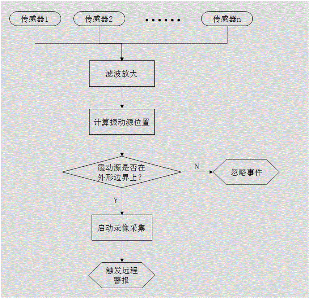
[0043] The present invention also proposes a collision detection method, see image 3 , specifically, multiple sensors are installed on the vehicle body for collecting collision signals, applicable sensors include sensing devices with piezoelectric effects, such as piezoelectric ceramics or piezoelectric films; it can also be an array of acoustic sensors, such as Including the microphone array and its MEMS system.

[0044] Including the following steps:

[0045] Step 1: The sensor detects the mechanical wave generated by the collision and transmits it to the central processing unit, and the central processing unit calculates the coordinates of the collision source according to the time difference between the mechanical wave reaching different sensors;

[0046] Step 2: Compare the coordinates of the collision source with the preset coordinates of the vehicle outline to determine whether the location of the collision source is on the boundary of the outline;

[0047] Step 3, if ...


PUM


Abstract

The invention relates to a vehicle collision alarming and recording triggering device and a detection method thereof, wherein the collision alarming and recording triggering device comprises multiple sensors, multiple image capturing devices, a central processing unit and an alarm and is characterized in that the sensors are arranged on the edge of a vehicle shell or in a carriage, and are used for collecting a collision signal; the image capturing devices are arranged on the edge of the vehicle shell or in the carriage, and is used for capturing video or audio information after collision occurs; the sensors and the image capturing devices are controlled by the central processing unit and achieve data exchange; the central processing unit is configured to analyze the collision signal in order to determine position coordinates of a collision source, comparing the position coordinates of the collision source with preset vehicle outline coordinates, and then judging whether collision occurs; and if the collision occurs, the central processing unit enables the image capturing devices and the alarm.

Description

technical field [0001] The invention relates to the technical field of intelligent Internet of Vehicles, in particular to a device for triggering a vehicle collision alarm and recording by a vehicle and a detection method thereof. Background technique [0002] Traditional driving recorders rely only on cameras and image processing to determine whether a collision has actually occurred. They can only treat objects approaching as suspected collisions. Therefore, it is necessary to continuously record and identify the surrounding conditions of the vehicle. It is not easy to retrieve evidence after the event, and it is time-consuming and labor-intensive to watch and search for suspected events in a large amount of video content. At the same time, due to the limitation of the power supply, it is impossible to record the events that occur after the car is turned off for a long time. In addition, there is a risk that the battery will be too low to start the engine. As a kind of au...

Claims


Application Information

Patent Timeline
IPC IPC(8): H04N5/225H04N7/18B60R21/0136G07C5/08G08B25/01
CPCH04N7/181G07C5/0891G08B25/01B60R21/0136B60R2300/8073H04N23/54H04N23/555
Inventor 杜朝亮穆佳昆叶智锐郭洪峰牛纪祥李文杰
Owner BEIJING TAIFANG TECH CO LTD
Learn More