A manufacturing method of a plastic-encapsulated stator, a plastic-enclosed stator and an outer rotor motor
A technology of plastic-encapsulated stators and manufacturing methods, which is applied in the manufacture of motor generators, stator/rotor bodies, electrical components, etc., can solve the problem of lack of magnetic flux concentration effect permanent magnet flux utilization, reduce the market competitiveness of motor products, and the outer rotor Problems such as low motor operation efficiency, to achieve the effect of convenient production and installation, strong combination, and improved utilization
- Summary
- Abstract
- Description
- Claims
- Application Information
AI Technical Summary
Problems solved by technology
Method used
Image

Examples
Embodiment 1
[0038] Embodiment 1: This embodiment is a manufacturing method of a plastic-encapsulated stator, which consists of the following steps:
[0039] Step 1) Making the stator core: stacking and assembling several annular stator punching pieces 101 with the annular yoke 11 and a plurality of stator teeth 12 protruding from the outer edge of the annular yoke 11 to form the stator core 1;
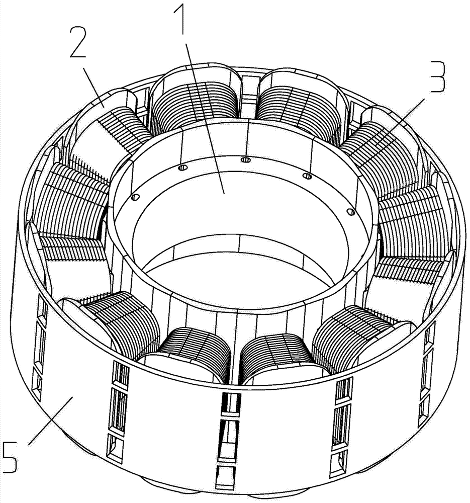
[0040] Step 2) Winding: install end insulation 2 at both ends of the stator core 1, and then wind the coil winding 3 and install it on the end insulation 2 of the stator teeth 12;
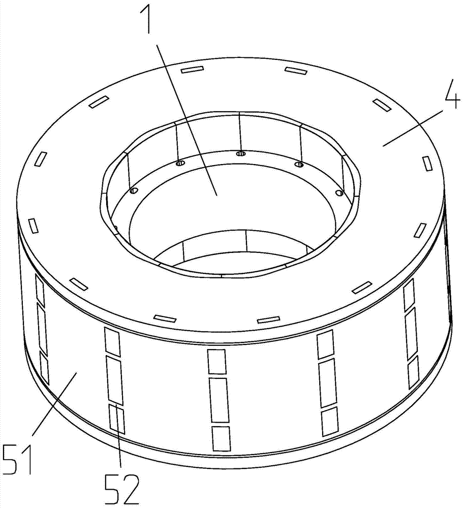
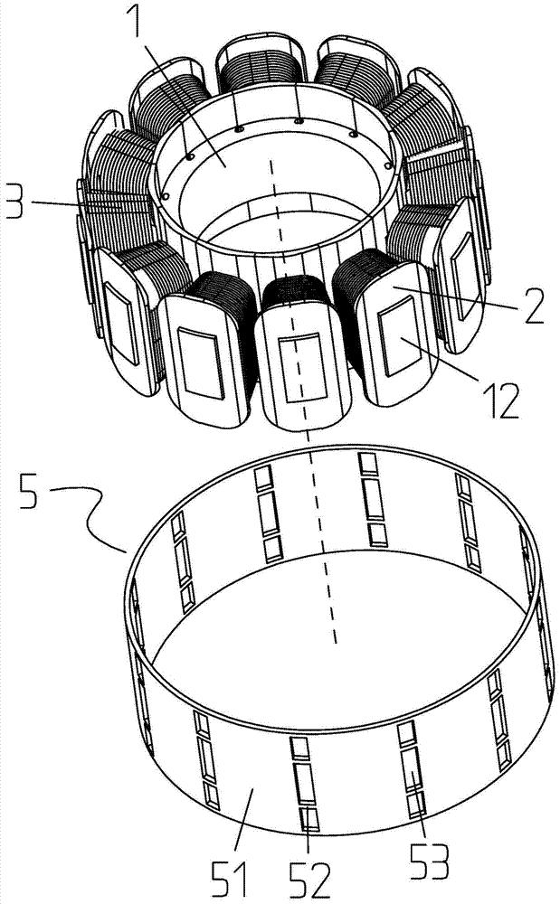
[0041] Step 3) Installing the magnetic guide: put the magnetic guide 5 outside the stator core 1 where the coil winding 3 has been wound, and make the outer side wall of the stator teeth 12 closely contact with the inner side wall of the magnetic guide 5;
[0042] Step 4) Plastic sealing: The stator core 1 with the magnetic guide 5 formed in step 3) is integrally injected to form a plastic package 4, and the stator co...
Embodiment 2
[0043] Embodiment two: if figure 1 , figure 2 , image 3 , Figure 4 with Figure 5 As shown, the present invention is a molded stator, including a stator core 1, end insulation 2, coil windings 3 and a molded body 4, the stator core 1 includes an annular yoke 11 and an outer edge of the annular yoke 11 A number of stator teeth 12 protruding from the upper part, a wire groove 13 is formed between two adjacent stator teeth 12, and the end insulation 2 is injected and installed on the end face of the stator core 1 and the stator teeth 12 The outer wall is exposed, and the coil winding 3 is wound and installed on the end insulation 2. It also includes a ring-shaped magnetic guide 5, and the magnetic guide 5 is placed outside the stator tooth 12. The exposed outer wall of the stator tooth 12 is connected to the The inner side wall of the magnetic conducting part 5 is closely attached together, and the stator core 1, the end insulation 2, the coil winding 3 and the magnetic co...
Embodiment 3
[0047] Embodiment three: as Figure 1 to Figure 9 As shown, the present embodiment is an outer rotor motor, which includes a rotating shaft 6, an outer rotor 7, a plastic-encapsulated stator 8 and a base 9. A sleeve seat 91 protrudes downward from the middle of the base 9, and a bearing is installed inside the sleeve seat 91. 10. The plastic-sealed stator 8 is set on the outside of the sleeve seat 91, the outer rotor 7 is sleeved on the outside of the plastic-sealed stator 8, the rotating shaft 6 is located inside the sleeve seat 91 and supported on the bearing 10, and one end of the rotating shaft 6 is connected from the sleeve Seat 91 protrudes and connects with outer rotor 7, said plastic-sealed stator 8 includes stator core 1, end insulation 2, coil winding 3 and plastic-sealed body 4, said stator core 1 includes annular yoke 11 and A number of stator teeth 12 protruding from the outer edge of the annular yoke 11, a wire slot 13 is formed between two adjacent stator teeth ...
PUM
 Abstract
Description
Claims
Application Information
 - R&D
- Intellectual Property
- Life Sciences
- Materials
- Tech Scout
- Unparalleled Data Quality
- Higher Quality Content
- 60% Fewer Hallucinations
Browse by: Latest US Patents, China's latest patents, Technical Efficacy Thesaurus, Application Domain, Technology Topic, Popular Technical Reports.
© 2025 PatSnap. All rights reserved.Legal|Privacy policy|Modern Slavery Act Transparency Statement|Sitemap|About US| Contact US: help@patsnap.com