Ripple bed
A technology of a wave bed and a bed body, applied in the field of wave bed, can solve the problems of unrelaxed muscles, muscle stiffness, bone deformation, etc., and achieve the effect of preventing muscle stiffness, avoiding space waste, and avoiding bone deformation.
- Summary
- Abstract
- Description
- Claims
- Application Information
AI Technical Summary
Problems solved by technology
Method used
Image
Examples
Embodiment 1
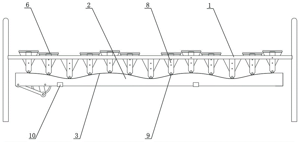
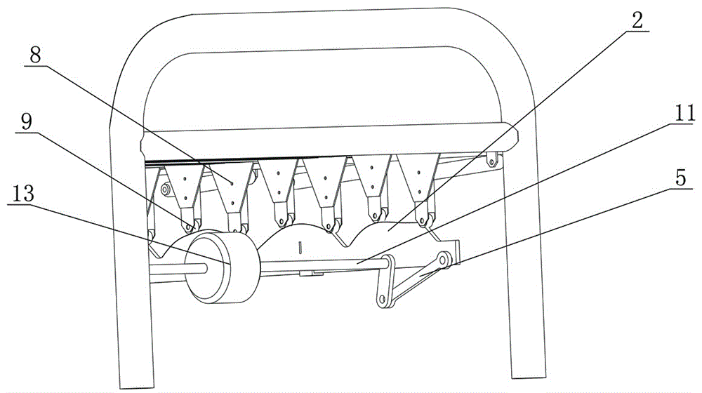
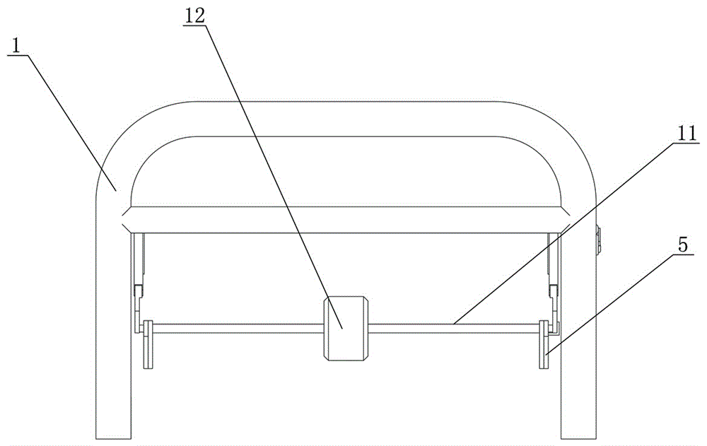
[0031] like Figure 1-3 As shown, a wave bed includes a bed body 1, a bed board, two wave rails 2 respectively installed on both sides of the bed body and a first power mechanism, wherein the upper end face of the wave rail 2 is a wave-shaped end face 3. The bed body 1 is provided with a horizontal slideway 10 extending from the head of the bed to the end of the bed, the undulating track 2 is slid inside the horizontal slideway 10, and the first power mechanism drives the undulating track 2 performing horizontal reciprocating motion in the horizontal slideway 10, the first power mechanism includes a motor 12, a reducer connected to the motor 12, a rotating shaft 11 connected to the reducer, and a crank connection connected to the rotating shaft 11 A rod mechanism 5 , the output end of the crank linkage mechanism 5 is connected to the undulating track 2 .
[0032] The bed board includes several strip plates 6 evenly laid on the bed body 1, guide rods 8 are arranged at both end...
Embodiment 2
[0035] like Figure 4 and Figure 5 As shown, the difference between this embodiment and Embodiment 1 is that it also includes a flat track 14 and a second power mechanism, the second power mechanism is a first cam mechanism 13, and the upper end surface of the flat track 14 is a plane, so The flat rail 14 is vertically slidingly matched with the bed body 1 through the slider 15, the upper end surface of the flat rail 14 is set corresponding to the pulley 9, and the first cam mechanism 13 can drive the flat rail 14 to Move to the upper end surface of the smooth track 14 to be flush with the uppermost end of the wave track 2 and support the pulley 9 . The outer peripheral surface of the first cam mechanism 13 abuts against the lower end surface of the leveling track 14 , and the vertical displacement of the leveling track 14 is realized through the rotation of the cam.
[0036] When the undulating track 2 is damaged, or during maintenance, the second power mechanism is operat...
Embodiment 3
[0038] like Figure 6 As shown, the difference between this embodiment and the above embodiments is that it also includes a third power mechanism, the third power mechanism is a second cam mechanism 16, and the main horizontal slideway 10 is vertically connected to the bed body 1. The upper sliding fit, the horizontal slideway 10 and the bed body 1 are fixed by a latch structure, the second cam mechanism 16 abuts against the lower end surface of the horizontal slideway 10, and can drive the horizontal slideway 10 during the rotation process And the lifting motion of the undulating track, when it rises to the highest position, it is the position of the normal use state, and when it is lowered to the low position, the support to the strip plate 6 is eliminated, and the bed body 1 becomes a flat bed body, which improves flexibility. higher. The place where the undulating track 2 is connected to the first power mechanism is equipped with a quick-installation structure. When repla...
PUM
 Abstract
Description
Claims
Application Information
 - R&D
- Intellectual Property
- Life Sciences
- Materials
- Tech Scout
- Unparalleled Data Quality
- Higher Quality Content
- 60% Fewer Hallucinations
Browse by: Latest US Patents, China's latest patents, Technical Efficacy Thesaurus, Application Domain, Technology Topic, Popular Technical Reports.
© 2025 PatSnap. All rights reserved.Legal|Privacy policy|Modern Slavery Act Transparency Statement|Sitemap|About US| Contact US: help@patsnap.com


