Cyclone separator

A cyclone separator and flow separation technology, applied in cyclone devices, separation methods, dispersed particle separation, etc., can solve the problems of limited applicable working conditions, limited pressure bearing capacity of devices, and difficulty in ensuring the original separation efficiency, etc. Achieve the effect of eliminating liquid entrainment, eliminating backflow, and not blocking maintenance workload

Pending Publication Date: 2016-10-26
安德油气工艺技术(天津)有限公司
View PDF12 Cites 8 Cited by
  • Summary
  • Abstract
  • Description
  • Claims
  • Application Information

AI Technical Summary

Problems solved by technology

Common cyclone separators mostly enter the device with tangential inlet, but this tangential inlet restricts the pressure bearing capacity of the device
At the same time, the fixed spinning parts are designed based on certain working condition parameters, and there are limitations in the scope of applicable working conditions. Once the working conditions change greatly, the original separation efficiency may be difficult to guarantee

Method used


Image

  • Cyclone separator
  • Cyclone separator
  • Cyclone separator

Examples


Embodiment Construction

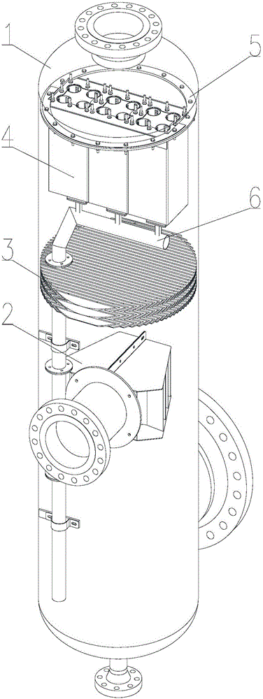
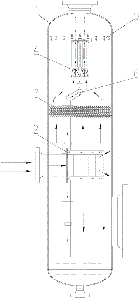
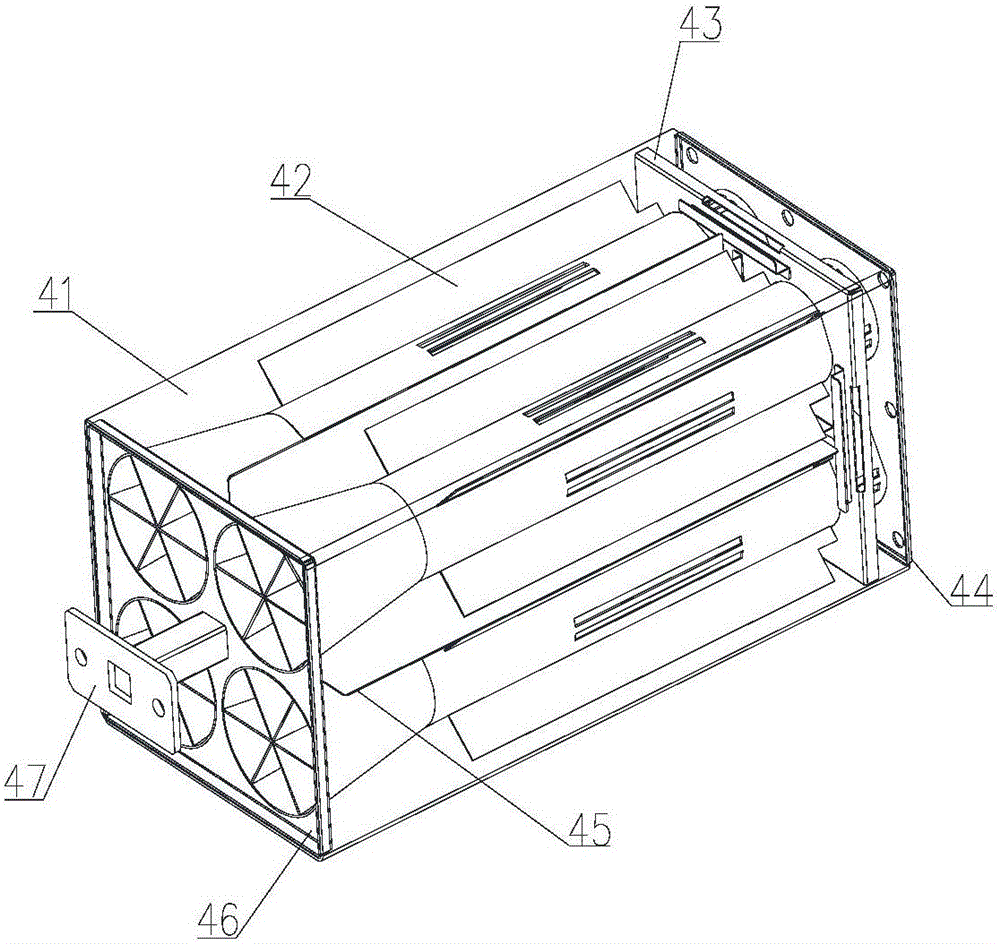
[0017] The specific implementation manner of the present invention will be described in detail below in conjunction with the accompanying drawings and preferred embodiments. Such as Figure 1-Figure 2 As shown, a cyclone separator includes a container body 1, a blade type inlet pre-separation device 2 is installed at the inlet of the container body, and a blade type or wire mesh structure demister is installed inside the container body 3. The demister is located on the upper part of the vane-type inlet pre-separation device, and the upper part of the demister is equipped with a multi-tube axial flow cyclone separation device 4, and the multi-tube axial flow cyclone separation device can pass The fixing plate 5 is disassembled and fixed inside the main body of the container, and the lower part of the multi-tube axial flow cyclone separation device is connected with a drain pipe 6, and the drain pipe communicates with the demister and extends to the lower part of the main body o...


PUM


Abstract

The invention relates to the technical field of gas-liquid separator parts, in particular to a cyclone separator. The cyclone separator comprises a container body. A blade type inlet pre-separation device is installed at the position of an inlet of the container body. A blade type or wire-mesh-structured mist eliminator is installed in the container body. The mist eliminator is located at the upper portion of the blade type inlet pre-separation device. A multi-pipe axial flow cyclone separation device is installed at the upper portion of the mist eliminator. The multi-pipe axial flow cyclone separation device is fixed in the container body through a detachable fixing plate. A draining pipe is connected to the lower portion of the multi-pipe axial flow cyclone separation device. The draining pipe communicates with the mist eliminator and extends towards the lower portion of the container body. According to the cyclone separator, the total liquid removing efficiency is high and can be higher than 98%, the capability of treating tiny mist drops is very high, and the problem of overload liquid resistance of liquid does not exist.

Description

technical field [0001] The invention relates to the technical field of gas-liquid separator components, in particular to a cyclone separator. Background technique [0002] Multi-tube axial flow cyclone separation device is an important process element in fluid separation in oil (gas) field development. It has a wide range of applications. Oil and gas field production equipment; suitable for gas separation in high-pressure, high-yield offshore oil and gas fields; especially for users with high separation technology requirements, this technology is their first choice, and the market demand space is large. At present, the technology of this equipment is completely controlled by foreign countries, and there is no competition in the same industry or other domestic production enterprises. Common cyclone separators mostly enter the device with tangential inlet, but this tangential inlet restricts the pressure bearing capacity of the device. At the same time, the fixed spinning pa...

Claims


Application Information

Patent Timeline
Patent Type & Authority Applications(China)
IPC IPC(8): B04C9/00B04C3/00B01D45/02B01D45/08B01D45/16
CPCB01D45/02B01D45/08B01D45/16B04C3/00B04C9/00B04C2009/004B04C2003/006B04C2003/003
Inventor 冯建军
Owner 安德油气工艺技术(天津)有限公司
Why Eureka
Try Eureka