Eureka AIR delivers breakthrough ideas for toughest innovation challenges, trusted by R&D personnel around the world.

Box carrying and stacking machine

A palletizer, No. 1 technology, applied in the direction of manipulators, program-controlled manipulators, chucks, etc., can solve the problems of waste and energy consumption, and achieve the effect of saving energy

Inactive Publication Date: 2016-10-26
XIAN UNIV OF FINANCE & ECONOMICS
View PDF5 Cites 7 Cited by
  • Summary
  • Abstract
  • Description
  • Claims
  • Application Information

AI Technical Summary

Problems solved by technology

[0003] At present, when the palletizing manipulator driven by the motor is used in the industry, if it is necessary to hover the goods in mid-air, it will consume a lot of energy, and this energy is equivalent to wasting in vain. At present, the use of manipulators is increasing The more popular, if not improved, this kind of useless energy consumption will be more and more

Method used


Image

  • Box carrying and stacking machine
  • Box carrying and stacking machine
  • Box carrying and stacking machine

Examples


Embodiment Construction

[0017] In order to make the technical means, creative features, goals and effects achieved by the present invention easy to understand, the present invention will be further described below in conjunction with specific embodiments.

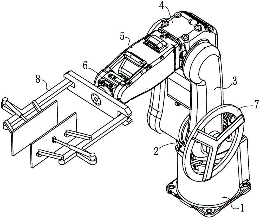
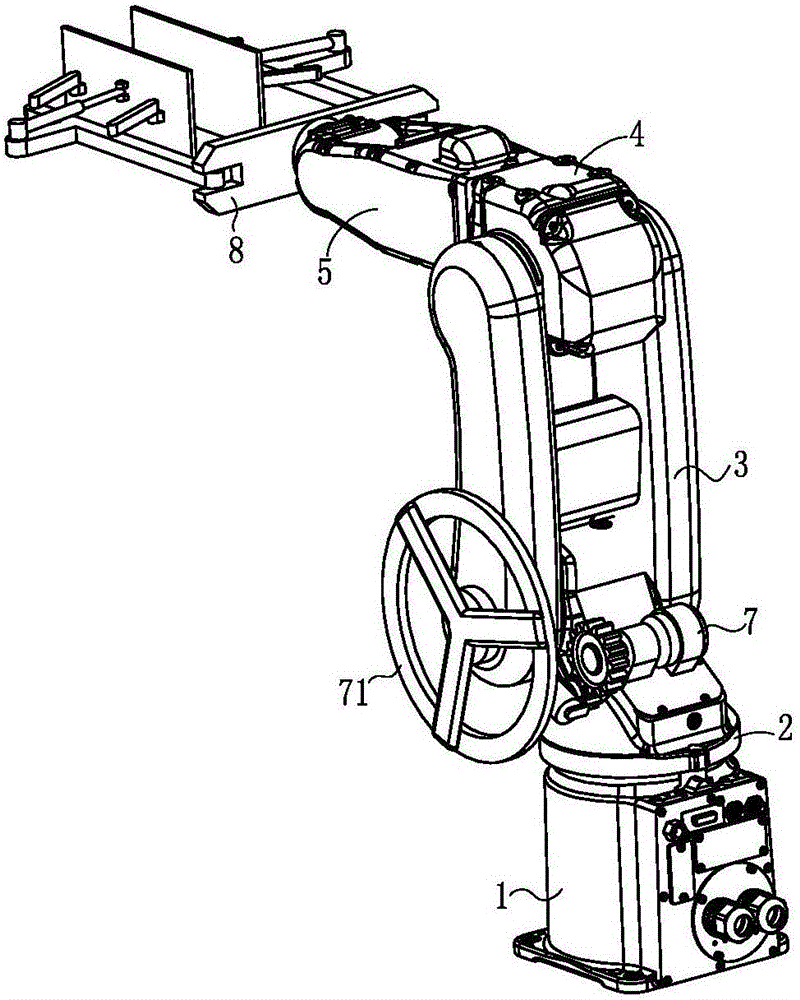
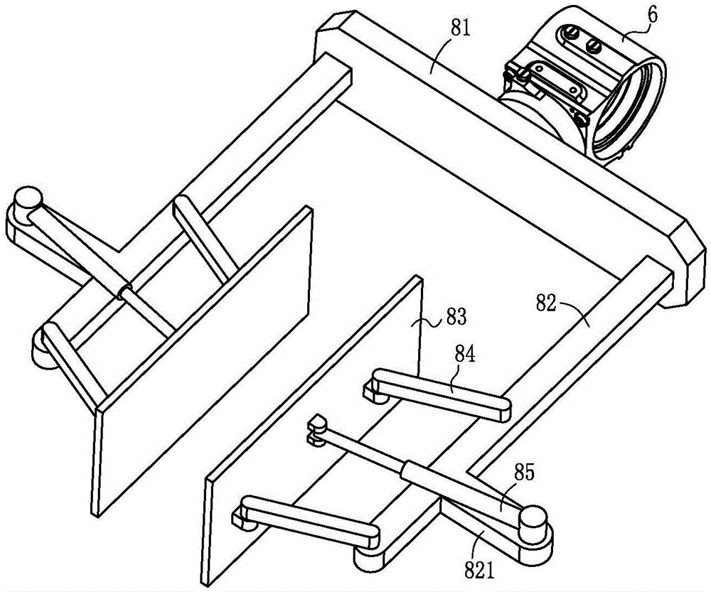
[0018] Such as figure 1 , figure 2 , image 3 , Figure 4 , a kind of case palletizing machine of the present embodiment comprises a base 1, a No. 1 transverse rotation joint 2, a No. 1 longitudinal rotation joint 3, a No. 2 longitudinal rotation joint 4, a No. 2 transverse rotation joint 5, a connecting terminal 6, and a Motion control device 7 and clamping device 8.

[0019] The No. 1 horizontal rotation joint 2 is arranged above the base 1 and is rotationally connected with the base 1; the No. 1 longitudinal rotation joint 3 is in the shape of an "H", and the bottom of the No. 1 longitudinal rotation joint 3 clamps the No. 1 lateral rotation joint. The joint 2 is hinged with it; the No. 2 longitudinal rotation joint 4 is hinged above the N...


PUM


Abstract

The invention relates to the field of stacking machinery, specifically to a box carrying and stacking machine. The box carrying and stacking machine comprises a base, a transverse rotational joint I, a longitudinal rotational joint I, a longitudinal rotational joint II, a transverse rotational joint II, a connecting tail end, a brake control device and a clamping device, wherein the brake control device is arranged on the transverse rotational joint I and comprises a brake disc, a brake motor, a transmission, a driving gear, a rotating shaft and a roller; the brake disc is fixed on the longitudinal rotational joint I; the brake motor is fixed on the transverse rotational joint I below the brake motor and is connected with the driving gear through the transmission; the rotating shaft is arranged on the transverse rotational joint I and is rotationally connected with the transverse rotational joint I; the roller is arranged on the rotating shaft; and the clamping device is arranged on the connecting tail end. According to the box carrying and stacking machine, the brake control device is arranged between mechanical arms, suspension of the mechanical arms is controlled by changing a mode of friction between the mechanical arms, and the mechanical joints have no energy loss in a suspension state, and thus energy can be greatly saved.

Description

technical field [0001] The invention relates to the field of palletizing machinery, in particular to a case palletizing machine. Background technique [0002] At present, in the field of industrial automation production, various special machines or mechanical arms are used to carry and stack materials to improve operating efficiency and overall productivity. According to the different conditions of the production line and the volume and weight of the material, these devices have different shapes. Compared with special-purpose machines, robotic arms have been widely used in the field of material handling and stacking due to their small footprint, simple structure, flexible operation, and flexible operations. The structural forms of the manipulator are more representative, such as the general-purpose articulated industrial manipulator, or the SCARA-shaped plane coordinate manipulator, etc. [0003] At present, when the palletizing manipulator driven by the motor is used in t...

Claims


Application Information

Patent Timeline
IPC IPC(8): B25J9/04B25J15/02
CPCB25J9/045B25J15/0266
Inventor 刘长苗
Owner XIAN UNIV OF FINANCE & ECONOMICS
Why Eureka
Eureka Blog
Learn More