Environment perception device and information acquisition method applicable to environment perception device

A technology of environmental perception equipment and sensors, which is applied in the direction of re-radiation, transportation and packaging, and re-radiation of electromagnetic waves. Accuracy, ensure the coincidence of the field of view, avoid the effect of poor contact

Inactive Publication Date: 2016-10-26
BAIDU ONLINE NETWORK TECH (BEIJIBG) CO LTD
4 Cites 26 Cited by

AI-Extracted Technical Summary

Problems solved by technology

[0003] However, when the above-mentioned method is used to obtain fused data, on the one hand, discretely designed cameras and lidars can easily cause problems such as poor contact and noise triggering in a high-vibration and high-interference vehicle environment
On the other hand, due to the difference in shape and viewing angle ...

Method used

[0021] In this embodiment, the camera sensor and the lidar sensor can be rigidly connected, so that the environmental perception device has good shock resistance, and the integrated electronic circuit design can ensure the stability of the connection and ...

Abstract

The invention discloses an environment perception device and an information acquisition method applicable to the environment perception device. One embodiment of the environment perception device comprises a camera sensor and a laser radar sensor which are integrated, and a control unit. The control unit is connected with the camera sensor and the laser radar sensor simultaneously. The control unit is used for inputting trigger signals in the camera sensor and the laser radar sensor simultaneously. On the one hand, the camera sensor and the laser radar sensor are designed to be integrated, the problems of poor contact, noise triggering and the like easily caused in the high- vibration high-interference vehicle environment are avoided, the camera sensor and the laser radar sensor are accurately simultaneously triggered, so that high quality data fusion is obtained, and further the environment perception accuracy is improved; on the other hand, the camera sensor and the laser radar sensor are guaranteed to have the consistent overlapped field of vision.

Application Domain

Autonomous decision making processElectric/fluid circuit +2

Technology Topic

RadarPattern perception +6

Image

  • Environment perception device and information acquisition method applicable to environment perception device
  • Environment perception device and information acquisition method applicable to environment perception device
  • Environment perception device and information acquisition method applicable to environment perception device

Examples

  • Experimental program(1)

Example Embodiment

[0013] The application will be further described in detail below with reference to the drawings and embodiments. It can be understood that the specific embodiments described here are only used to explain the related invention, but not to limit the invention. In addition, it should be noted that, for ease of description, only the parts related to the relevant invention are shown in the drawings.
[0014] It should be noted that the embodiments in the application and the features in the embodiments can be combined with each other if there is no conflict. Hereinafter, the present application will be described in detail with reference to the drawings and in conjunction with embodiments.
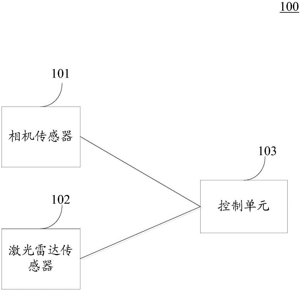
[0015] Please refer to figure 1 , Which shows a schematic structural diagram of an embodiment of the environment sensing device according to the present application.
[0016] Such as figure 1 As shown, the environment sensing device 100 includes: an integrated camera sensor 101 and a lidar sensor 102, and a control unit 103. The control unit 103 is connected to the camera sensor and the lidar sensor at the same time; wherein the control unit 103 is used to simultaneously input a trigger signal to The camera sensor 101 and the lidar sensor 102 can simultaneously trigger the camera sensor 101 and the lidar sensor 102 to collect images and laser point cloud data.
[0017] In this embodiment, the camera sensor 101 and the lidar sensor 102 may be adjacently fixed in the module. For example, the lidar sensor 102 may be superimposed on the camera sensor 101. The camera sensor 101 and the lidar sensor 102 may have a uniform overlapping field of view. The control unit 103 can be connected to the camera sensor 101 and the lidar sensor 102 at the same time. When it is necessary to control the camera sensor 101 and the lidar sensor 102 to collect images and laser point cloud data, the control unit 103 can send to the camera sensor 101 and the lidar sensor 102 at the same time The trigger signal simultaneously triggers the camera sensor 101 and the lidar sensor 102 to collect images and laser point cloud data. Make the camera sensor and the lidar sensor work synchronously, and collect the image and laser point cloud data at the same time.
[0018] Please refer to figure 2 , Which shows a schematic diagram of the effect that the camera sensor and the lidar sensor have the same overlapping field of view.
[0019] in figure 2 In the figure, a camera sensor 201 and a lidar sensor 202 are shown. The lidar sensor 202 can be superimposed on the camera sensor 201, and adjacently fixed in the module. The camera sensor 201 and the lidar sensor 202 may have a uniform overlapping field of view.
[0020] In some optional implementations of this embodiment, the camera sensor and the lidar sensor are rigidly connected.
[0021] In this embodiment, the camera sensor and the lidar sensor can be rigidly connected, so that the environment sensing device has good seismic performance, and the integrated electronic circuit design can ensure the stability of the connection and the shielding of electromagnetic interference. To avoid problems such as poor contact and noise triggering in a vehicle environment with high vibration and high interference, it can accurately trigger the camera sensor and the lidar sensor at the same time.
[0022] In some optional implementations of this embodiment, the trigger signal input ends of the camera sensor and the lidar sensor are connected to the same trigger signal input line to receive the trigger signal sent by the control unit through the trigger signal input line.
[0023] In this embodiment, the trigger signal input terminals of the camera sensor and the lidar sensor can be connected to the same trigger signal input line, so that the control unit can send trigger signals to the camera sensor and the lidar sensor through the trigger signal input line to trigger the camera sensor and the lidar sensor. The lidar sensor is working at the same time, collecting images and laser point cloud data at the same time.
[0024] In some alternative implementations of this embodiment, the control unit includes: a clock subunit and a clock synchronization subunit for generating a trigger signal according to a preset frequency; wherein, the clock synchronization subunit is used for receiving an external clock signal and using The external clock signal calibrates and synchronizes the clock subunit. The external clock signal includes: GPS clock signal, NTP (Network Time Protocol, Network Time Protocol) signal, that is, network time signal.
[0025] In this embodiment, the clock subunit can be used to generate a trigger signal for triggering the camera sensor and the lidar sensor according to a preset frequency. The clock synchronization subunit can be used to receive an external clock signal, and the external clock signal can be used to calibrate and synchronize the clock subunit.
[0026] In some optional implementation manners of this embodiment, the environment sensing device further includes: a digital model unit for acquiring the conversion relationship between the coordinate system of the camera sensor and the coordinate system of the lidar sensor.
[0027] In some optional implementations of this embodiment, the environment sensing device further includes: a preprocessing unit for adding time stamp information to the image and laser point cloud data; based on the coordinate system of the camera sensor and the coordinate system of the lidar sensor The conversion relationship between the two, the color information corresponding to each laser point data in the laser point cloud data is queried in the image, and the laser point cloud data corresponding to the color information is generated.
[0028] In this embodiment, the conversion relationship between the coordinate system of the camera sensor and the coordinate system of the lidar sensor can be obtained through the digital model unit. After the control unit sends a trigger signal to the camera sensor and the lidar sensor, which triggers the camera sensor and the lidar sensor to collect images and laser point cloud data at the same time, the preprocessing unit can be used to add time stamp information to the image and laser point cloud data. Information can be used to indicate the collection time of images and laser point cloud data. Then, according to the conversion relationship between the coordinate system of the camera sensor and the coordinate system of the lidar sensor acquired by the digital model unit, the color information corresponding to each laser point data in the laser point cloud data can be queried in the collected image , Generate laser point cloud data corresponding to color information. Thus, the external perception system can further process the laser point cloud data corresponding to the color information.
[0029] Please refer to image 3 , Which shows an exemplary structure diagram of the environment sensing device according to the present application.
[0030] Environmental sensing equipment includes camera sensors, lidar sensors, and control chips. The camera sensor and the lidar sensor can be fixed next to each other in the module, and the viewing angles are consistent, that is, they have a consistent overlapping field of view. The control chip is connected to the camera sensor and the lidar sensor at the same time, and the control chip can adopt a field programmable gate array. The control chip can send trigger signals to the camera sensor and the lidar sensor at the same time, thereby triggering the camera sensor and the lidar sensor to simultaneously collect images and laser point cloud data.
[0031] In this embodiment, the control chip can be connected to an external trigger signal source, and the external trigger signal source can be used to send a trigger signal to the camera sensor and the lidar sensor. For example, the trigger signal can come from an external algorithm processor, which triggers the camera sensor and the lidar sensor to collect images and laser point cloud data according to the algorithm requirements.
[0032] In this embodiment, the control chip may include a clock, and the clock may be used to generate a trigger signal for triggering the lidar sensor of the camera sensor at a preset frequency. The control chip can be connected to an external clock source. The external clock source can be a GPS clock signal source or a network time signal source. The external clock source can be used to calibrate and synchronize the clock of the control chip.
[0033] In an embodiment, the control chip may record the trigger time stamp of the image and laser point cloud data collected after the camera sensor and the lidar sensor are simultaneously triggered. The trigger timestamp can be used to indicate the time when the image and laser point cloud data were collected. The data transmission interface configured by the control chip can be used to transmit the trigger time stamp to an external processor or external storage. The data transmission interface may include but is not limited to: an Ethernet interface and a USB interface.
[0034] Please refer to Figure 4 , Which shows a process 400 of an embodiment of an information acquisition method applied to an environment sensing device according to the present application. The method includes the following steps:
[0035] Step 401: Receive a data collection instruction.
[0036] In this embodiment, the environment sensing device can be installed on an autonomous vehicle. Environmental sensing equipment includes integrated camera sensors and lidar sensors. The camera sensor and the lidar sensor can be fixed adjacently in the module. For example, a lidar sensor can be superimposed on the camera sensor. The camera sensor and the lidar sensor can have a consistent overlapping field of view.
[0037] In this embodiment, when a camera sensor and a lidar sensor are required to collect images and laser point cloud data, for example, when the process of identifying obstacles running in an autonomous vehicle control system requires images and laser point clouds When data, you can generate data collection instructions.
[0038] In this embodiment, a data collection process for controlling the camera sensor and lidar sensor to collect images and laser point cloud data can be created, and the data collection process can be used to receive data collection instructions.
[0039] Step 402: Send a trigger signal to the camera sensor and the lidar sensor at the same time.
[0040] In this embodiment, after receiving the data collection instruction in step 401, trigger signals can be sent to the camera sensor and the lidar sensor at the same time, and the camera sensor and the lidar sensor are triggered to collect images and laser point cloud data at the same time.
[0041] In this embodiment, the trigger signal input ends of the camera sensor and the lidar sensor can be connected to the same trigger signal input line, and the trigger signal can be sent to the camera sensor and the lidar sensor through the trigger signal input line, and the camera sensor and the lidar sensor can be triggered at the same time. In the working state, the image and laser point cloud data are collected at the same time.
[0042] In some optional implementations of this embodiment, it further includes: receiving an external clock signal; using the external clock signal to synchronize the preset clock, the external clock signal includes: GPS clock signal, network time signal, preset clock To generate a trigger signal according to a preset frequency.
[0043] In this embodiment, the trigger signal used to trigger the camera sensor and the lidar sensor may be generated by a preset clock. The preset clock may be used to generate a trigger signal for triggering the lidar sensor of the camera sensor at a preset frequency.
[0044] In this embodiment, an external clock signal can be received, and the preset clock can be calibrated and synchronized using the external clock signal.
[0045] In some optional implementation manners of this embodiment, it further includes: acquiring a conversion relationship between the coordinate system of the camera sensor and the coordinate system of the lidar sensor.
[0046] In some optional implementations of this embodiment, it further includes: adding time stamp information to the image and laser point cloud data; based on the conversion relationship between the coordinate system of the camera sensor and the coordinate system of the lidar sensor, in the image Query the color information corresponding to each laser point data in the laser point cloud data, and generate the laser point cloud data corresponding to the color information.
[0047] In this embodiment, after the camera sensor and the laser radar sensor are triggered to simultaneously collect the image and laser point cloud data, time stamp information can be added to the image and laser point cloud data. The time stamp information can be used to represent the image and laser point cloud. Data collection time. Then, according to the conversion relationship between the acquired coordinate system of the camera sensor and the coordinate system of the lidar sensor, the color information corresponding to each laser point data in the laser point cloud data can be queried in the collected image, and the corresponding Laser point cloud data with color information. Thus, the external perception system can further process the laser point cloud data corresponding to the color information.
[0048] The above description is only a preferred embodiment of the present application and an explanation of the applied technical principles. Those skilled in the art should understand that the scope of the invention involved in this application is not limited to the technical solutions formed by the specific combination of the above technical features, and should also cover the technical solutions based on the above technical features without departing from the inventive concept. Other technical solutions formed by any combination of its equivalent features. For example, the above-mentioned features and the technical features disclosed in this application (but not limited to) with similar functions are mutually replaced to form a technical solution.

PUM

no PUM

Description & Claims & Application Information

We can also present the details of the Description, Claims and Application information to help users get a comprehensive understanding of the technical details of the patent, such as background art, summary of invention, brief description of drawings, description of embodiments, and other original content. On the other hand, users can also determine the specific scope of protection of the technology through the list of claims; as well as understand the changes in the life cycle of the technology with the presentation of the patent timeline. Login to view more.

Similar technology patents

Wiring device for auxiliary power device for vehicle

InactiveCN107946836Aavoid poor contactSolve the cumbersome wiring process
Owner:斯凯伦动力设备科技(兴化)有限公司

Audio device

Owner:SHENZHEN HORN AUDIO

Classification and recommendation of technical efficacy words

  • improve accuracy
  • avoid poor contact

Golf club head with adjustable vibration-absorbing capacity

InactiveUS20050277485A1improve grip comfortimprove accuracy
Owner:FUSHENG IND CO LTD

Direct fabrication of aligners for arch expansion

ActiveUS20170007366A1improve accuracyimproved strength , accuracy
Owner:ALIGN TECH

Stent delivery system with securement and deployment accuracy

ActiveUS7473271B2improve accuracyreduces occurrence and/or severity
Owner:BOSTON SCI SCIMED INC

Method for improving an HS-DSCH transport format allocation

InactiveUS20060089104A1improve accuracyincrease benefit
Owner:NOKIA SOLUTIONS & NETWORKS OY

Catheter systems

ActiveUS20120059255A1increase selectivityimprove accuracy
Owner:ST JUDE MEDICAL ATRIAL FIBRILLATION DIV
Why Eureka
Try Eureka