A connecting rod imitation leg type walking mechanism and method

A connecting rod mechanism and walking mechanism technology, applied in the field of connecting rod imitation leg type walking mechanism, can solve the problems of difficult driving and control methods, difficult to achieve ideal effect, complicated structure, etc., and achieve simple structure, ingenious operation, easy installation of parts little effect

Active Publication Date: 2017-12-19
SOUTHEAST UNIV
View PDF6 Cites 1 Cited by
  • Summary
  • Abstract
  • Description
  • Claims
  • Application Information

AI Technical Summary

Problems solved by technology

The existing walking mechanism has a complex structure, most of which are humanoid leg joints, and the degrees of freedom are generally greater than 5. The driving and control methods are particularly difficult, and it is difficult to achieve the desired effect. The cost is high and it is difficult to promote

Method used


Image

  • A connecting rod imitation leg type walking mechanism and method
  • A connecting rod imitation leg type walking mechanism and method
  • A connecting rod imitation leg type walking mechanism and method

Examples


Embodiment Construction

[0022] The present invention will be further described below in conjunction with the accompanying drawings.

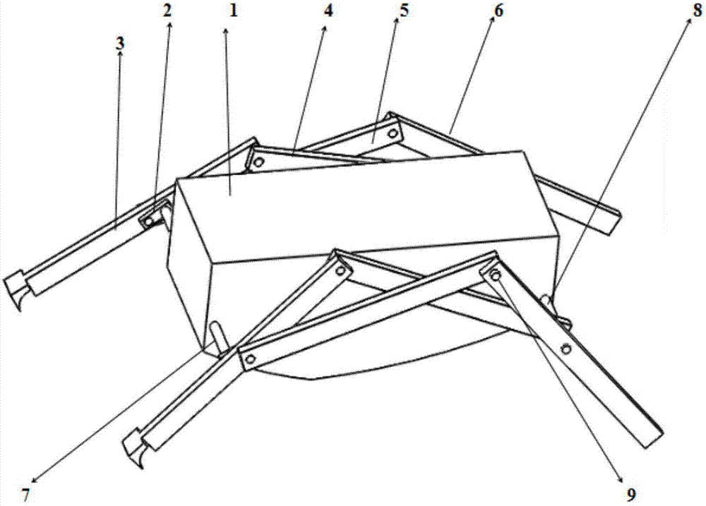
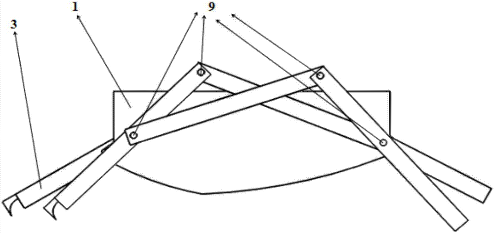
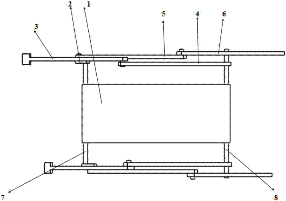
[0023] like figure 1 , figure 2 and image 3 Shown is a connecting rod imitation leg type walking mechanism, which is characterized in that it includes a main body 1, a shaft and a connecting rod mechanism; the connecting rod mechanism is connected to the shaft through a crank 2;

[0024] The link mechanism is symmetrically distributed on both sides of the main body 1, and the link mechanism on each side includes a front foot link mechanism and a rear foot link mechanism; the shaft includes a front axle 7 and a rear axle 8;

[0025] The forefoot link mechanism comprises a forefoot short link 3 and a forefoot long link 4, and the motion tracks of the two links are on the same plane; the forefoot short link 3 is connected to the front axle 7, and the forefoot long link 4 is connected to the rear axle 8; One end of the two connecting rods is connected to each other; ...


PUM


Abstract

The invention discloses a connecting rod leg-imitated type travelling mechanism and method. The connecting rod leg-imitated type travelling mechanism comprises a main body, shafts and connecting rod mechanisms. The connecting rod mechanisms are connected with the shafts through crankshafts and symmetrically distributed on the two sides of the main body. Each connecting rod mechanism on each side comprises a forefoot connecting rod mechanism body and a hindfoot connecting rod mechanism body. The shafts comprise the front shafts and the rear shafts. One end of each crankshaft and the corresponding front shaft are in rotation pair constraint, and the other end of the crankshaft is connected with a corresponding short forefoot connecting rod and a corresponding long hindfoot connecting rod so that the short forefoot connecting rod and the long hindfoot connecting rod can be driven to rotate. The short forefoot connecting rod and a corresponding long forefoot connecting rod are in rotation pair constraint. Each long forefoot connecting rod and the corresponding rear shaft are in rotation pair constraint. The method comprises the following steps that the crankshafts drive the short forefoot connecting rods to start moving, and then other connecting rods are driven to move in sequence, so that the whole travelling mechanism moves forwards. The travelling mechanism is simple in structure, traveling can be completed through the simple crankshaft-connecting rod structure, and the connecting rod mechanisms have the characteristics of being capable of bearing large loads, convenient to manufacture and capable of reducing production cost and later maintenance cost.

Description

technical field [0001] The invention relates to a walking device, in particular to a connecting rod imitation leg type walking mechanism and method. Background technique [0002] Commonly used walking mechanisms are tires and crawlers, while legged walking is supported by multiple points, and the way of exchanging legs is used to drive the whole device to walk through the reaction force of friction generated between the legs and the ground. The legged walking mechanism has good obstacle-surmounting ability , Superior maneuverability and ground adaptability. The common leg poses are generally left-right symmetrical, such as the six-legged pose or the quadruped-legged pose, and the quadruped-legged pose is more common at present. The existing walking mechanism has a complex structure, most of which are humanoid leg joints, and the degrees of freedom are generally greater than 5. The driving and control methods are particularly difficult, it is difficult to achieve the desired...

Claims


Application Information

Patent Timeline
Patent Type & Authority Patents(China)
IPC IPC(8): B62D57/032
CPCB62D57/032
Inventor 陈开
Owner SOUTHEAST UNIV
Why Eureka
Try Eureka