
Tension quick release device for belt conveyor

A technology of releasing device and belt conveyor, applied in the direction of conveyor, transportation and packaging, which can solve the problems of system impact, large parking acceleration and parking inertia force, equipment damage, etc.

Active Publication Date: 2017-12-29
科大重工集团(郎溪)有限公司
View PDF10 Cites 0 Cited by
  • Summary
  • Abstract
  • Description
  • Claims
  • Application Information

AI Technical Summary

Problems solved by technology

However, when there is an emergency stop or an accidental power failure of the equipment, the parking acceleration and parking inertial force will become very large due to the lack of reliable and controllable parking means, which will cause a great impact on the system, especially the tension on the belt conveyor. The system is most impacted, causing equipment damage

Method used


Image

  • Tension quick release device for belt conveyor
  • Tension quick release device for belt conveyor

Examples


Embodiment Construction

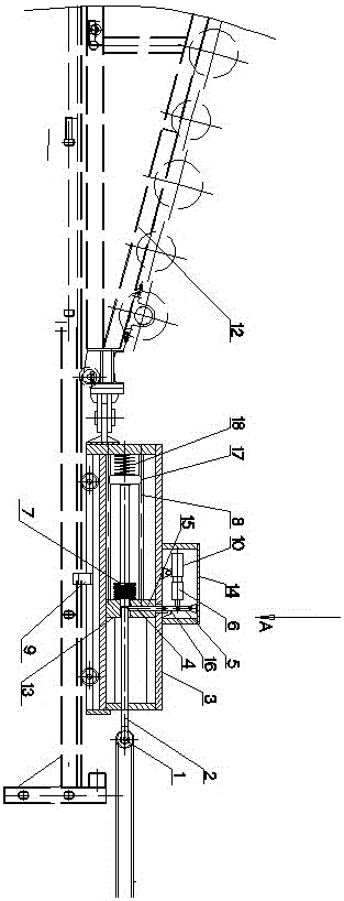
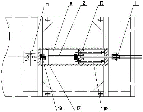
[0011] according to figure 1 , 2 As shown, the present invention relates to a tension quick release device for a belt conveyor, which includes an auxiliary vehicle 3 arranged on the belt conveyor track, the left end of the auxiliary vehicle 3 connects with the tensioning vehicle 12 of the belt conveyor through a pin shaft 11 connected, the auxiliary vehicle 3 is divided into two cavities by a partition 13, the right end of the auxiliary vehicle 3 is provided with a pull rod 2 protruding from the right side wall of the auxiliary vehicle 3, and the right end of the pull rod 2 A pulley block 1 is provided, and the pulley block 1 is rollingly connected with the wire rope of the belt conveyor. A guide rod 8 is fixed in the left cavity of the auxiliary vehicle 3, and the left end of the pull rod 2 passes through the partition plate 13 along the The guide rod 8 slides, and a hole 15 is provided on the partition plate 13 corresponding to the position of the pull rod 2, and a locking ...


PUM


Abstract

The invention discloses a quick tensile force relieving device for a belt conveyer. The quick tensile force relieving device comprises an auxiliary vehicle arranged on a belt conveyer rail, wherein the left end of the auxiliary vehicle is connected with a tensioning vehicle; a pull rod which extends out of the side wall on the right side of the auxiliary vehicle is arranged at the right end of the auxiliary vehicle; a pulley block is arranged at the end part of the right side of the pull rod; the pulley block is connected with a steel wire rope of the belt conveyer in a rolling manner; a guide rod is fixedly arranged in a cavity on the left side of the auxiliary vehicle; the left end of the pull rod penetrates through a partition plate to slide along the guide rod; a hole is formed in the partition plate; a locking rod which moves up and down along the hole is arranged in the hole; a protective cover is further arranged at the upper part of the auxiliary vehicle; the top of the protective cover is hinged to a first hinged plate; the other end of the first hinged plate is connected with a valve core of an electromagnetic valve and the upper end of a second hinged plate through a shaft; the lower end of the second hinged plate is hinged to the upper end of the locking rod; and a crawl stopping hook is arranged in the middle position of the bottom of the auxiliary vehicle. Through the adoption of the structure, the effects that the structure is compact, the operation is reliable, the device is safe and stable, when the vehicle stops suddenly or the device is out of power accidentally, tensile force can be quickly relieved, and a belt conveyer tensioning system is prevented from being damaged are achieved.

Description

technical field [0001] The invention relates to a tension quick release device for a belt conveyor. Background technique [0002] With the continuous increase of the transport capacity and transport distance of the belt conveyor, the dynamic inertial force of the system when it starts and stops also increases. Since the advanced controllable soft start technology has been successfully applied to the belt conveyor, the starting inertia force of the belt conveyor has been able to be controlled within the allowable range. However, when there is an emergency stop or an accidental power failure of the equipment, the parking acceleration and parking inertial force will become very large due to the lack of reliable and controllable parking means, which will cause a great impact on the system, especially the tension on the belt conveyor. The system is most affected, causing equipment damage. Contents of the invention [0003] The purpose of the present invention is to provide a ...

Claims


Application Information

Patent Timeline
Patent Type & Authority Patents(China)
IPC IPC(8): B65G23/44
CPCB65G23/44
Inventor 车新宁郁清林李秀云
Owner 科大重工集团(郎溪)有限公司
Learn More