
Indoor testing device for simulating grouting pile end post-grouting and testing method

An indoor test and post-grouting technology, which is applied in the test of foundation structure, construction, foundation structure engineering, etc., can solve the problems of thick sediment at pile ends, lack of theoretical support, and difficulty in hole cleaning, and achieve the effect of convenient excavation

Inactive Publication Date: 2016-10-26
TONGJI UNIV
View PDF4 Cites 15 Cited by
  • Summary
  • Abstract
  • Description
  • Claims
  • Application Information

AI Technical Summary

Problems solved by technology

But cast-in-situ piles also have the following two problems: (1) During the process of hole formation, a certain thickness of sediment appears at the bottom of the pile due to construction disturbance, especially when the hole depth is deep, it is difficult to clean the hole, resulting in excessive thickness of sediment at the pile end , the pile tip resistance decreases too much; (2) hole formation and mud wall protection lead to softening of the pile side and pile tip soil, the pile tip displacement is too large after the pile is formed, and the pile tip resistance cannot be effectively exerted, etc.
However, in actual engineering operations, due to complex geological conditions, it is difficult to ensure the grouting effect, and there is also a lack of detection methods and technologies. There is also a lack of theoretical support for post-grouting technology at the pile tip, which affects the promotion and application of post-grouting technology at the pile tip

Method used


Image

  • Indoor testing device for simulating grouting pile end post-grouting and testing method
  • Indoor testing device for simulating grouting pile end post-grouting and testing method
  • Indoor testing device for simulating grouting pile end post-grouting and testing method

Examples


Embodiment

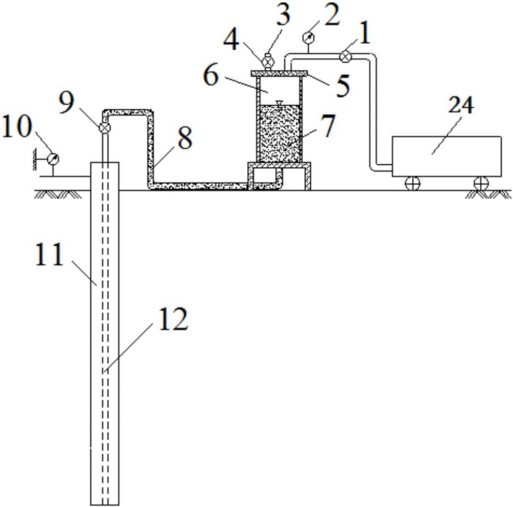
[0043] An indoor test device for simulating post-grouting of cast-in-situ piles, the connection of which is as follows figure 1 As shown, the device includes an air compressor 24, a slurry storage tank 6 and a model pile 11 connected in sequence, and a pressure regulating valve 1 and a pressure gauge 2 are arranged on the connecting pipeline between the air compressor 24 and the slurry storage tank 6, and the slurry storage tank The top of 6 is provided with flange top cover 5, and above flange top cover 5 is provided with pressure relief valve 4, and this pressure relief valve 4 communicates with atmosphere through pressure relief hole 3. Cement slurry is placed inside the grout storage tank 6, and the bottom of the grout storage tank 6 is connected to the model pile 11 through the grout inlet pipe 8 and the grouting valve 9. The grouting pipe 12 is inserted in the middle of the model pile, and a hundred Subtable 10 is mainly used to test the lifting displacement of the model...


PUM


Abstract

The invention relates to an indoor testing device for simulating grouting pile end post-grouting and a testing method. The indoor testing device comprises an air compressor, a grout storage tank and a model pile which are connected in sequence. A connection pipeline of the air compressor and the grout storage tank is provided with a pressure regulating valve and a pressure gauge. The top of the grout storage tank is provided with a flange top cover, and the bottom of the grout storage tank is connected with the model pile through a grout inlet pipe and a grouting valve. The model pile is inserted into a model groove. Compared with the prior art, the indoor testing device for simulating grouting pile end post-grouting and the testing method can be used for simulating a grouting process of in-situ grouting pile end post-grouting and is capable of well reflecting actual process procedures of pile end post-grouting, achieving pile end post-grouting of large-size model grouting piles of different soil layers and controlling the grouting pressure and the grouting quantity. By means of the testing result of the indoor testing device and the testing method, the actual working properties of foundation piles subjected to pile end post-grouting can be well reflected, revealing of a grouting mechanism of pile end post-grouting is facilitated, and a reference base is provided for design, construction and the like of pile end post-grouting of an actual pile foundation project.

Description

technical field [0001] The invention relates to the technical field of post-grouting engineering of cast-in-situ piles, in particular to an indoor test device and a test method for simulating post-grouting of cast-in-situ piles. Background technique [0002] With the development of my country's construction, cast-in-place pile foundations have been more and more widely used in urban high-rise buildings, port terminals, transportation and marine projects, because they are widely applicable to various soil conditions and the length-to-diameter ratio of piles can be With the advantages of flexible selection and high carrying capacity, it has become one of the main basic forms widely used in my country at this stage. The reasonable use of cast-in-situ pile foundation can not only effectively improve the bearing capacity of the foundation, reduce the settlement deformation of buildings (structures), but also improve the seismic performance of buildings (structures), so as to ensur...

Claims


Application Information

Patent Timeline
Patent Type & Authority Applications(China)
IPC IPC(8): E02D33/00E02D15/04
CPCE02D15/04E02D33/00E02D2250/003
Inventor 赵春风刘丰铭赵程于淼刘帆陶逸文
Owner TONGJI UNIV
Learn More