Steel structure bracket

A technology of steel structures and corbels, which is applied in the direction of building construction and construction, can solve the problems of inability to set up platforms, beams, and inconsistent appearance, and achieve the effect of simple structure, enhanced bearing capacity, and uniform appearance

Active Publication Date: 2016-10-26
李新华
View PDF7 Cites 1 Cited by
  • Summary
  • Abstract
  • Description
  • Claims
  • Application Information

AI Technical Summary

Problems solved by technology

This kind of structural setting brings many restrictions to the implementation of the steel structure. First, the appearance is complicated. Due to structural limitations, the length of the beam can only be set to the length between the two columns, and the ends of the beam beyond the length limit will not be able to be installed on the male legs of the two columns
The third is to limit the structure of steel structure products. For example, it is necessary to set up a lifting platform at a certain height. Since the ends of the beams of the existing structure need to be supported on the columns, if only one end has a column, the beam cannot be installed. , it is not possible to set the platform

Method used


Image

  • Steel structure bracket
  • Steel structure bracket
  • Steel structure bracket

Examples


Embodiment 1

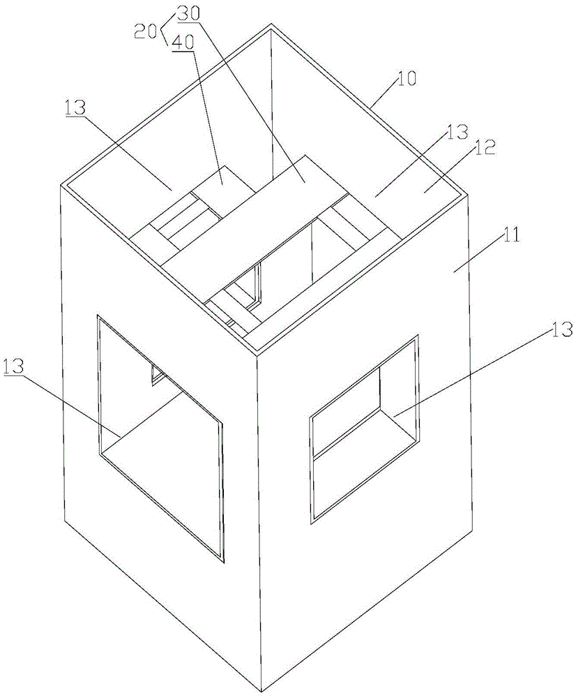
[0053] Such as figure 1 As shown, the steel structure corbel includes casing 10 and connector 20 . The cannula 10 has a cannula wall 11 which encloses a cannula lumen 12 . The sleeve tube wall 11 is provided with a first through hole 13 penetrating through the sleeve tube wall 11 . The shape of the casing wall 11 and the shape of the casing lumen 12 can be quadrangular or circular, and can also be selected as other shapes according to actual needs. The quadrilateral can be a rectangle, a square or other available shapes. In the example shown, the cannula wall 11 is rectangular and the cannula lumen 12 is also rectangular. The position and number of the first through holes 13 can be selected according to actual needs. In this embodiment, four first through holes 13 are respectively opened on the four sides of the quadrangular casing wall 11 . Every two is a group, and the positions of the two are aligned, and the size is the same.

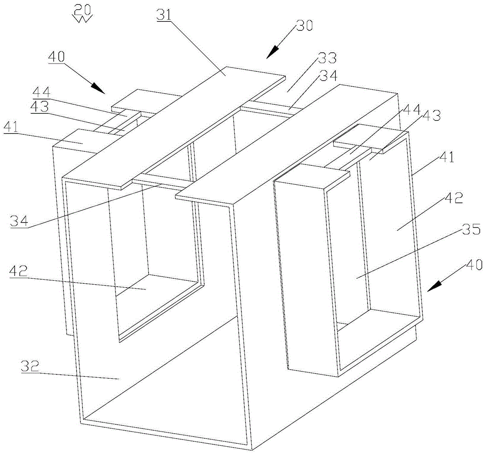
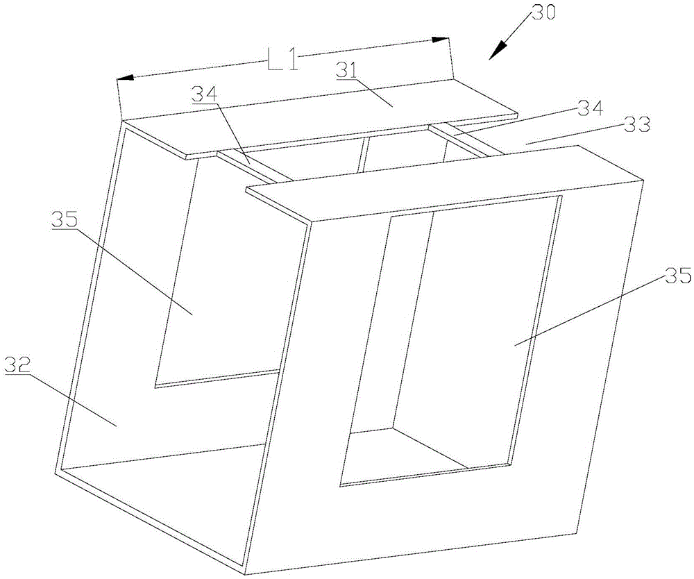
[0054] Such as figure 1 , figure 2 a...

Embodiment 2

[0062] Such as Figure 5 As shown, the steel structure corbel includes casing 10 and connector 20 . Sleeve 10 structure such as figure 1shown. The casing 10 has a casing wall 11, the casing wall 11 encloses a casing lumen 12, and the casing wall 11 is provided with a first through hole 13 penetrating through the casing wall 11 . The shape of the casing wall 11 and the shape of the casing lumen 12 can be quadrangular or circular, and can also be selected as other shapes according to actual needs. The quadrilateral can be a rectangle, a square or other available shapes. In the example shown, the cannula wall 11 is rectangular and the cannula lumen 12 is also rectangular. The position and number of the first through holes 13 can be selected according to actual needs. In this embodiment, four first through holes 13 are respectively opened on four surfaces of the rectangular casing wall 11 . Every two is a group, and the positions of the two are aligned, and the size is the ...

Embodiment 3

[0069] Figure 8 The internal structure of the cannula lumen is shown. like Figure 8 As shown, the steel structure corbel includes a casing 10 and a connecting piece 20 . Sleeve 10 structure such as figure 1 shown. The cannula 10 has a cannula wall 11 which encloses a cannula lumen 12 . The sleeve tube wall 11 is provided with a first through hole 13 penetrating through the sleeve tube wall 11 . The shape of the casing wall 11 and the shape of the casing lumen 12 can be quadrangular or circular, and can also be selected as other shapes according to actual needs. The quadrilateral can be a rectangle, a square or other available shapes. In the example shown, the cannula wall 11 is rectangular and the cannula lumen 12 is also rectangular. The position and number of the first through holes 13 can be selected according to actual needs. In this embodiment, four first through holes 13 are respectively opened on the four sides of the quadrangular casing wall 11 . Every two i...


PUM


Abstract

The invention discloses a steel structure bracket. The steel structure bracket is characterized by comprising a sleeve, the sleeve is provided with a sleeve wall which defines a sleeve cavity; a first through hole penetrating through the sleeve wall is formed in the sleeve wall; and the first through hole communicates with the sleeve cavity. The steel structure bracket can meet any design requirements for current reinforced concrete systems and lower the labor cost of construction and installation. The structure principle of the steel structure bracket is applied to a steel structure so as to solve the problems of beam continuity, structure fixing and node strength. The condition of beam top concrete pouring grooves is ingeniously used for welding, and the problem of steel structures is completely solved.

Description

technical field [0001] The invention specifically relates to a steel structure corbel. Background technique [0002] Steel structures are widely used in modern house construction. In a steel structure house, its structure consists of columns and beams. Uprights support beams. According to different load-bearing capacity requirements, beams are divided into main beams and secondary beams. The beam is supported by columns. In the prior art, the connection between the column and the beam is realized by using a male corbel structure. The positive corbel is arranged on the outer surface of the column. The ends of the beams are connected to the male corbels. This kind of structural setting brings many restrictions to the implementation of the steel structure. First, the appearance is complicated. Due to structural restrictions, the length of the beam can only be set to the length between the two columns, and the two ends of the beam beyond the length limit cannot be install...

Claims


Application Information

Patent Timeline
Patent Type & Authority Applications(China)
IPC IPC(8): E04B1/24E04B1/58
Inventor 李新华
Owner 李新华
Why Eureka
Try Eureka