Automobile warm-air

A warm air and automobile technology, applied in the direction of heat exchanger fixation, heat exchange equipment, fixed conduit components, etc., can solve problems such as leakage and scrapping, poor sealing, aging and damage of flat tubes, etc., to increase the overall rigidity and ensure Welding quality, effect of increasing cooling effect

Inactive Publication Date: 2008-07-23
许惠新
View PDF0 Cites 3 Cited by
  • Summary
  • Abstract
  • Description
  • Claims
  • Application Information

AI Technical Summary

Problems solved by technology

[0003] 1. Brazing is used in the production process. The biggest problem encountered in the production process is that the welding between the water chamber and the main piece is not strong, and the sealing is not good enough to leak and be scrapped.
[0004] 2. In the production process of automobile heating brazing, because the materials used for the heat dissipation belt and the main piece are different, the required welding temperature is different accordingly, so the contact part between the heat dissipation belt and the main piece will often be melted during one-time welding, which affects the The effective heat dissipation area of ​​the heat dissipation strip and the appearance quality of the product
However, this fixing method makes the connection between the side plate and the main plate not very firm and reliable, resulting in poor overall rigidity of the car heater, and at the same time cannot effectively protect the heat dissipation belt from damage
[0006] 4. Since the outlet of the water inlet pipe has flat pipes facing it, and the cooling water is corrosive to a certain extent, the water flow of these flat pipes facing it will be greater than that of other flat pipes, which will lead to rapid aging of these flat pipes destruction

Method used


Image

  • Automobile warm-air
  • Automobile warm-air
  • Automobile warm-air

Examples


Embodiment Construction

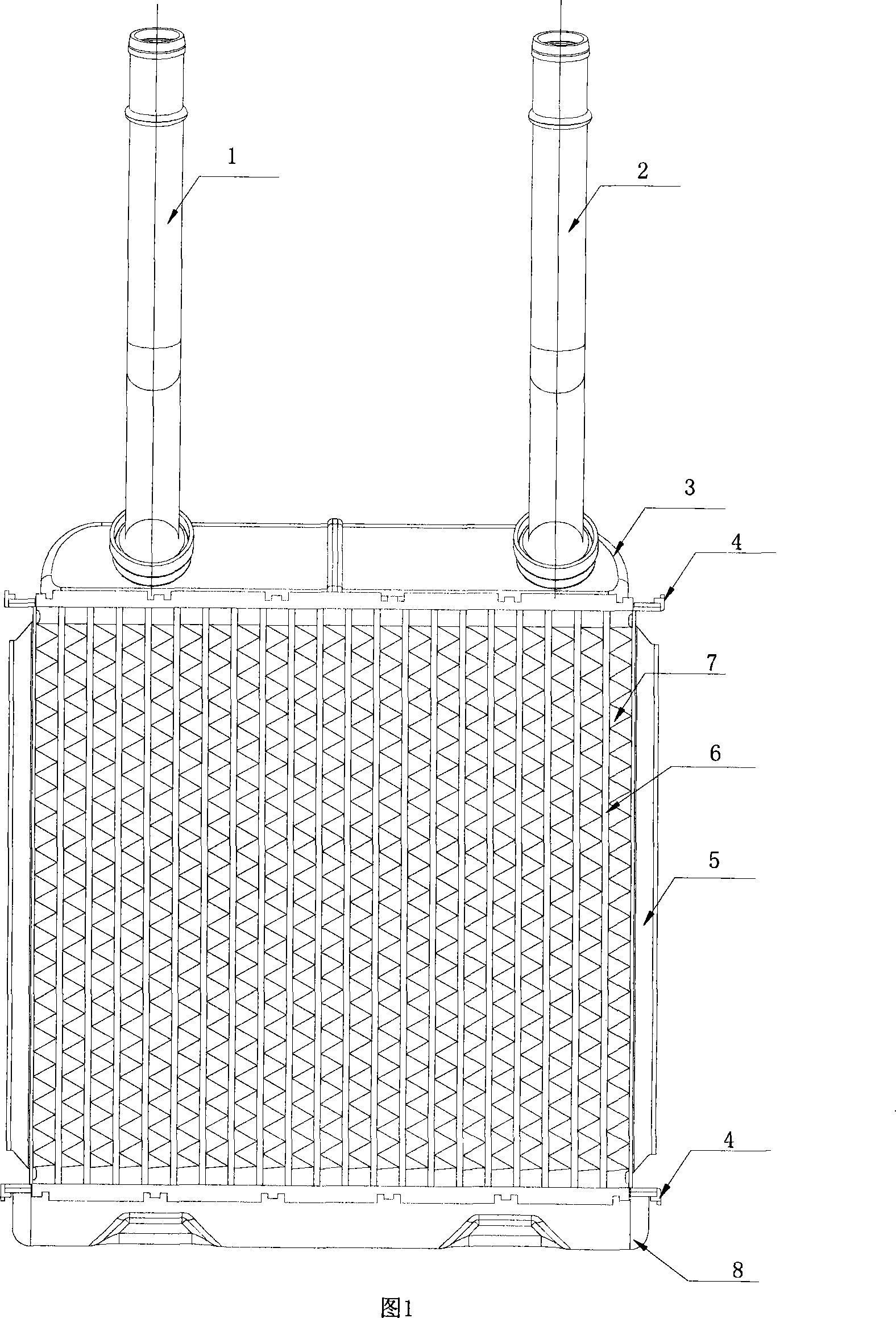
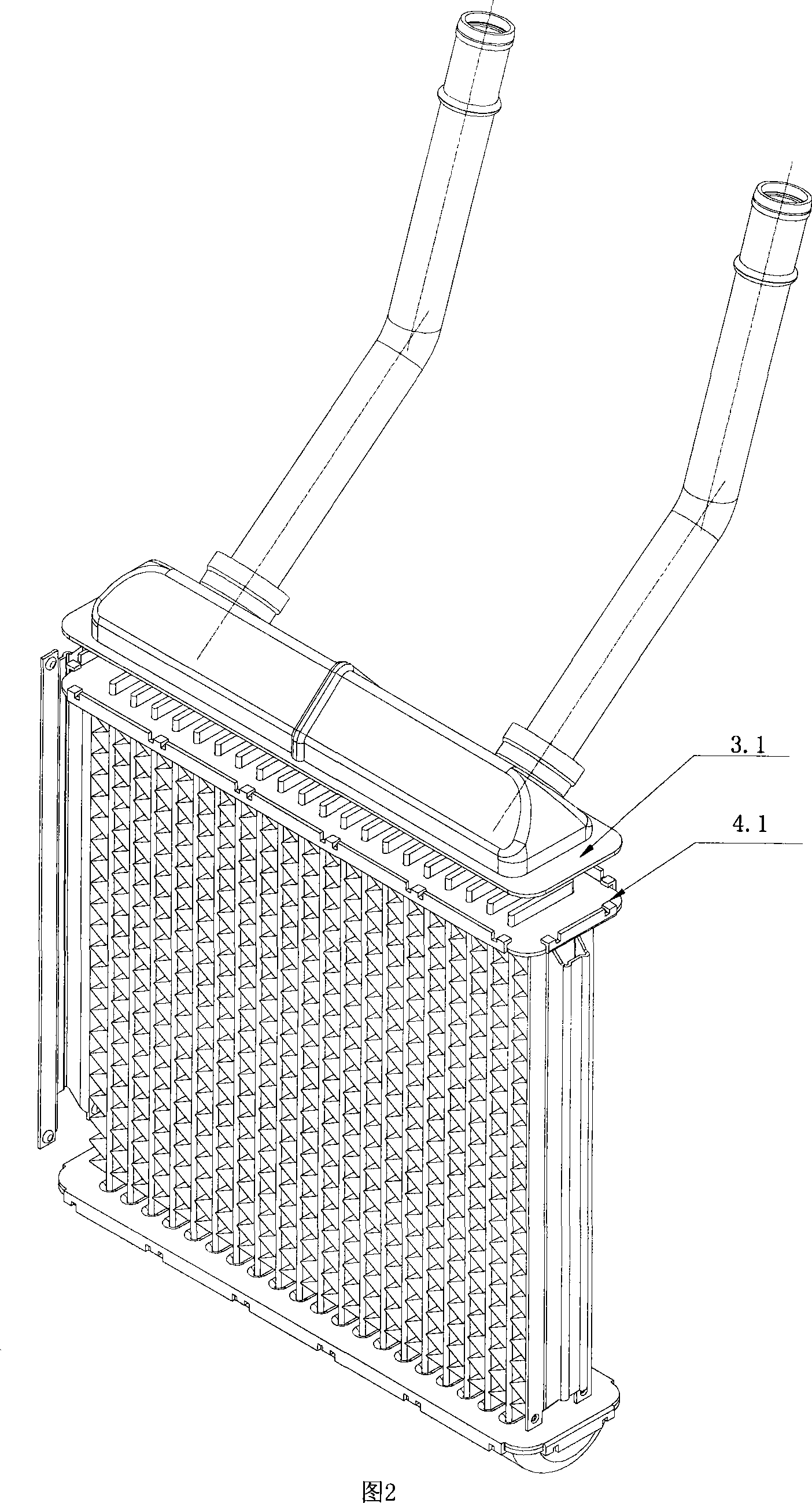
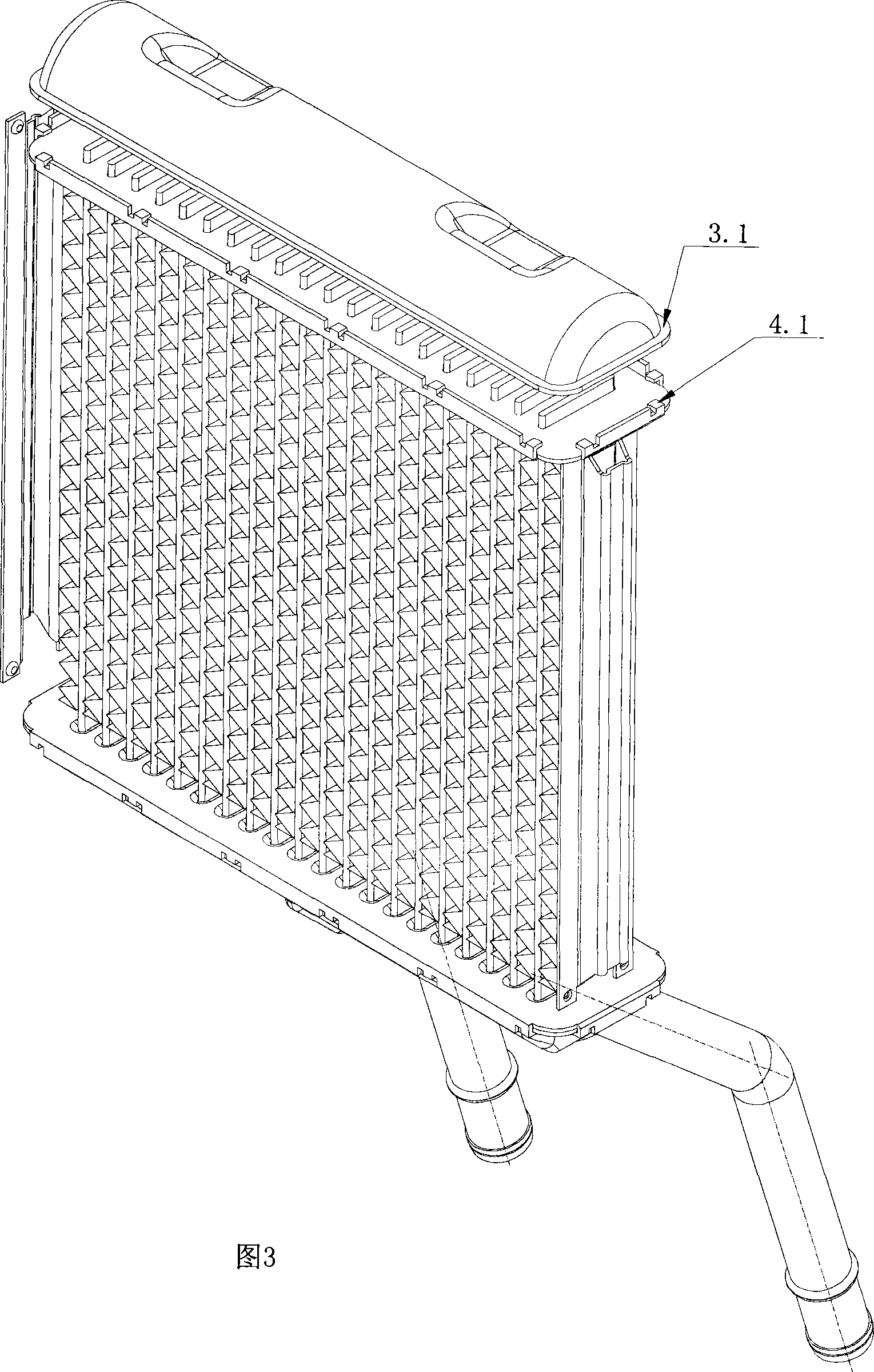
[0036] Referring to Figure 1, the car heater is structurally divided into eight parts: water inlet pipe 1, water outlet pipe 2, upper water chamber 3, lower water chamber 8, main piece 4, flat pipe 6, heat dissipation belt 7 and side plate 5. The main piece 4 is provided with several tooth pieces 4.1 around its connection with the upper water chamber 3 and the lower water chamber 8, as shown in Figures 2, 3, 4 and 5. When assembling, the teeth pieces 4.1 are engaged with the edge 3.1 of the joint (bottom) of the upper water chamber 3 and the lower water chamber 8 with the main piece 4, and then brazed, as shown in Figures 6 and 7. This structure can be applied to the connection between the main piece and the water chamber of all types of automobile heaters and engineering water tanks.

[0037] Described side plate 5 is respectively provided with two bulges 5.1 or two elbows 5.2 on the side wall of its position corresponding to the two ends of the heat dissipation strip 7, as s...


PUM


Abstract

The invention relates to an automobile heater, which comprises a water feeding chamber(3), a drain chamber(8), a water inlet pipe(1), a main leaf(4), a side board(5), a heat dissipation belt(7) and a flat tube(6); wherein a plurality of tooth bits (4.1) meshed at the bottom edge (3.1) of the water feeding chamber(3) and the drain chamber(8) are arranged at the periphery of the main leaf(4) at the joint between the water feeding chamber(3) and the drain chamber(8); two bulges (5.1) or elbows (5.2) are respectively arranged at the sidewall of the position of the side board(5) corresponding to both ends of the heat dissipation belt(7); a lug (4.2) occluded at the terminal of the side board(5) is positioned at the joint between the terminal of the side board(5)and the main leaf(4); a buffer plate(9) is arranged between the water outlet of the water inlet pipe(1) and the water inlet of flat tube(6) facing to the water outlet of the water inlet pipe(1). The automobile heater has the advantages that: the connection between the water chambers and the main leaf is firm, which can prevent the part melting and dropping of the heat dissipation belt in the process of welding production; the connection between the side board and the main leaf can be firm and reliable; and can make balanced water feeding flow of all flat tube.

Description

technical field [0001] The invention relates to a car heater, in particular to a connection structure between a water chamber and a main piece of the car heater. It belongs to the technical field of auto parts. Background technique [0002] The car heater is a car part that uses the cooling water of the car engine for heating. It is divided into eight parts in structure: water inlet pipe, water outlet pipe, upper water chamber, lower water chamber, main piece, flat pipe, heat dissipation belt and side plate. It mainly has the following deficiencies: [0003] 1. Brazing is used in the production process. The biggest problem encountered in the production process is that the welding between the water chamber and the main piece is not strong, and the sealing is not good enough to leak and be scrapped. [0004] 2. In the production process of automobile heating brazing, because the materials used for the heat dissipation belt and the main piece are different, the required weldi...

Claims


Application Information

Patent Timeline
Patent Type & Authority Applications(China)
IPC IPC(8): F28D1/053
CPCF28F2275/122F28D1/05366F28F9/001F28F9/0224F28F2275/04
Inventor 陈军许惠新
Owner 许惠新
Why Eureka
Try Eureka