
Pressure-tight wire connection device

A technology of wire connection and pressure-resistant sealing, which is applied in cable inlet sealing devices, cable installation, cable joints, etc., can solve the problems of complex structure of cable sealing components, unsatisfactory sealing effect, use of molds, etc., to achieve structural The effect of simplicity, low cost and convenient installation

Inactive Publication Date: 2015-04-29
LIUZHOU OVM MASCH CO LTD
View PDF7 Cites 1 Cited by
  • Summary
  • Abstract
  • Description
  • Claims
  • Application Information

AI Technical Summary

Problems solved by technology

[0003] The patent publication number is CN1380729A, and the invention patent application titled "Cable Cable Sealing Assembly" discloses a cable sealing assembly including a single standard sealing joint. The wire directly passes through the cable sealing assembly, and the inner sealing lip is used to tighten Seal the outer surface of the wire; the disadvantage is that because the outer layer of the cable (insulation layer or shielding layer) is soft and is an irregular circle, it is difficult for the sealing lip to complete the full circumference of the outer layer of the cable. Sealing, the sealing effect is not very ideal; moreover, the structure of the cable sealing assembly is complicated, and each part is made of plastic or rubber, which needs to be made by mold. For single-piece or small-batch production, the cost is too high

Method used


Image

  • Pressure-tight wire connection device
  • Pressure-tight wire connection device
  • Pressure-tight wire connection device

Examples


Embodiment Construction

[0035] The pressure-resistant and sealed wire connection device of the present invention in the form of threaded installation:

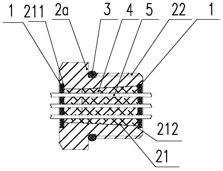
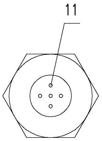
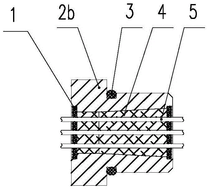
[0036] Such as Figure 1-1~Figure 1-2 As shown, the pressure-resistant and sealed wire connection device includes a branch line support plate 1, a joint 2, a sealing ring 3, a filling sealant 4, and a wire 5 used to communicate with the inside and outside of the tank;

[0037] The shape of the joint 2 is a cylinder with unequal diameters formed by a hexagonal cross-section at the large end and a circular cross-section at the small end. There is a through hole 21 inside, and steps 211 and 212 are respectively provided at both ends of the through hole. The outer edge of the cylinder at the small end has threads 22;

[0038] Five small holes 11 for threading wires 5 are arranged on the branching support plate 1;

[0039] In the assembled state, the two branch line support plates 1 are respectively placed on the steps 211 and 212 at both ends of the thr...


PUM

PropertyMeasurementUnit
Lengthaaaaaaaaaa

Abstract

The invention discloses a pressure-tight wire connection device which comprises sub-wire support plates, a joint, a seal ring, a filling and sealing material and wires for communicating the inner part and the outer part of a tank, wherein the joint is an unequal-diameter cylinder in the outline, which has a through hole formed by combining a straight hole with a taper hole; a large end of the taper hole faces the pressure gas direction; both ends of the through hole are respectively provided with steps; the joint is a screwed joint which has external threads on the outer diameter of the small end, or a flange joint, the large end of which is a flange plate; n small holes for threading the wires are formed in the sub-wire support plates; in assembly state, two sub-wire support plates are respectively placed on the steps at both ends of the through hole in the joint; m wires penetrate through the hole in the joint and n small holes corresponding to the sub-wire support plates; the through hole in the joint is filled with the filling and sealing material to bond the sub-wire support plates, the joint and the wires into a whole; the seal ring is located at cable entrances of the joint and a sealed tank; and n is not less than m, and n is not less than 1 and not greater than 20. The pressure-tight wire connection device is reliable in sealing under a certain gas pressure, simple in structure, and convenient to install.

Description

technical field [0001] The invention relates to a wire connection device, in particular to a pressure-resistant and sealed wire connection device. Background technique [0002] In some special equipment, in order to prolong the service life of components and reduce the electromagnetic interference of components to other peripheral equipment, it is often necessary to install these components in a closed metal container, and inject certain The inert gas under pressure isolates the components from the oxygen and water vapor in the atmosphere, so as to achieve the purpose of anti-oxidation and moisture resistance and prolong the service life of the components. At the same time, because it is installed in a closed metal container, the electromagnetic waves generated by the components are not easy to leak out, reducing their electromagnetic interference to other equipment; The power supply or communication of electrical components is a concern for everyone. [0003] The patent p...

Claims


Application Information

Patent Timeline
IPC IPC(8): H02G15/08H02G15/013
CPCH02G15/013H02G15/085
Inventor 梁利文李兴奎甘秋萍沈继荣杨文振
Owner LIUZHOU OVM MASCH CO LTD
Learn More