Steel structure

A technology of steel structure and pipe wall, applied in the direction of building structure, construction, etc., can solve the problems of inability to set up platforms, beams, and inconsistent appearance, and achieve the effect of simple structure, enhanced bearing capacity, and uniform appearance

Active Publication Date: 2016-10-26
李新华
View PDF9 Cites 6 Cited by
  • Summary
  • Abstract
  • Description
  • Claims
  • Application Information

AI Technical Summary

Problems solved by technology

This kind of structural setting brings many restrictions to the implementation of the steel structure. First, the appearance is complicated. Due to the structural limitation, the length of the beam can only be set as the length between the two supporting columns, and the two ends of the beam beyond the length limit cannot be installed on the male legs of the two suppor

Method used


Image

  • Steel structure
  • Steel structure
  • Steel structure

Examples


Embodiment 1

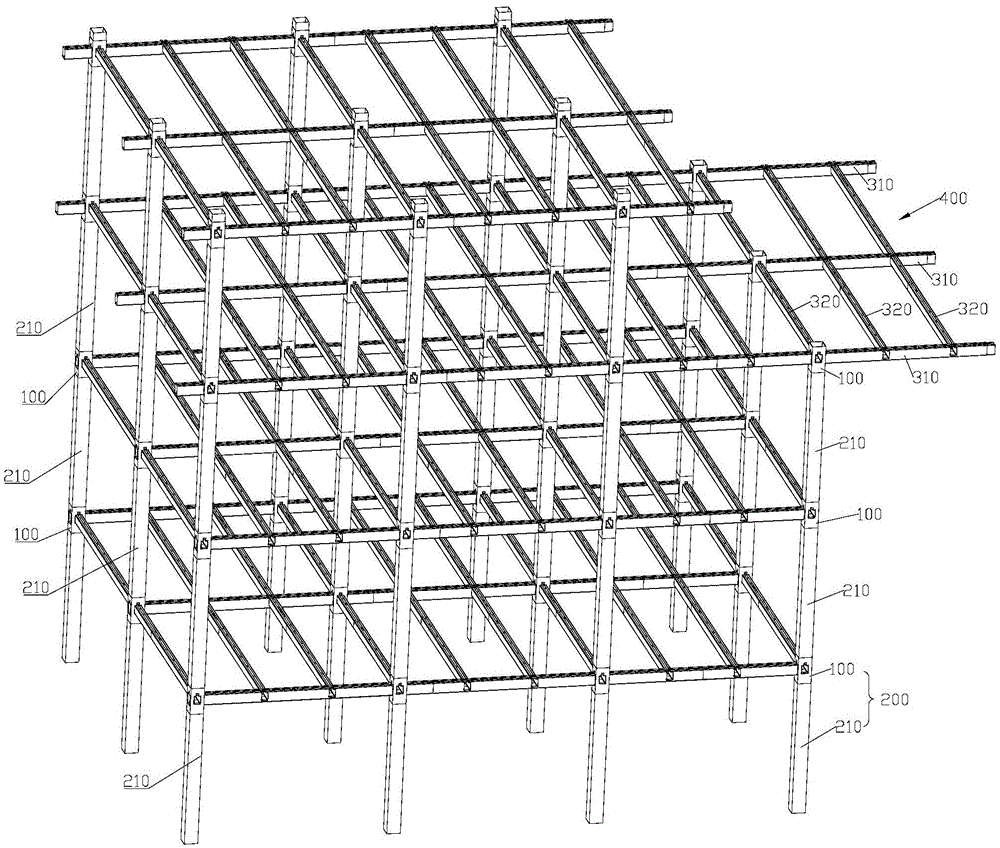
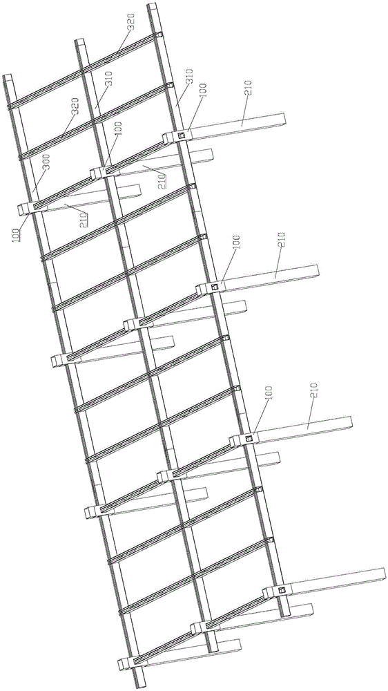
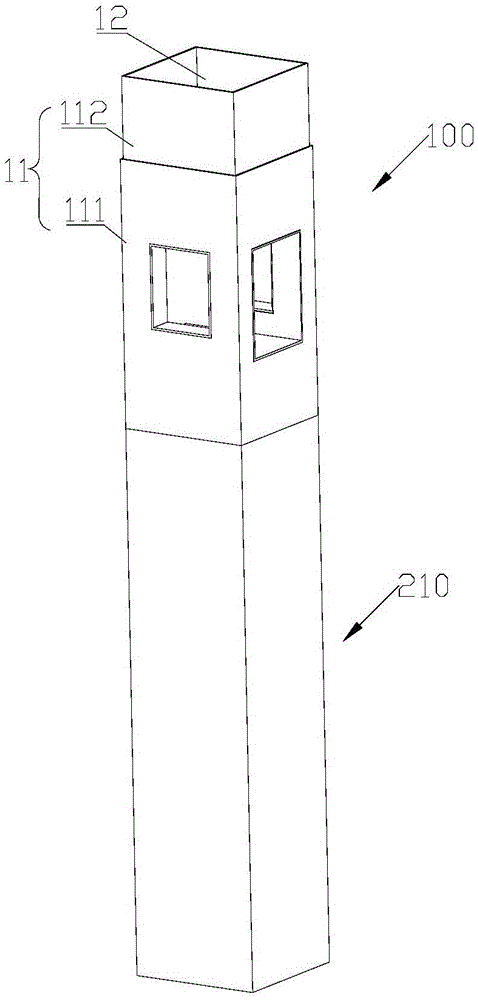
[0057] Such as figure 1 , figure 2 As shown, the steel structure includes multiple columns 200 , multiple main beams 310 and multiple secondary beams 320 . The column 200 includes a support column 210 and a corbel structure 100 . The corbel structure 100 is disposed at the end of the support column 210 . A plurality of support columns 210 are connected through the corbel structure 100 and are arranged in a multi-layer structure. On the right side of the third floor, there is a pick platform 400 . in such as figure 1 In the example shown, there are four layers. Such as figure 1 , figure 2 As shown, in each layer of steel structure, the main beam 310 and the secondary beam 321 pass through the corbel structure 100 . The corbel structure 100 connects the support column 210 with the main beam 310 and the secondary beam 320 . The support column 210 supports the main beam 310 and the secondary beam 320 . Each main beam 310 can be formed by connecting multiple sections, o...

Embodiment 2

[0068] Such as Figure 10 , Figure 11 As shown, the corbel structure in this embodiment is different from that in Embodiment 1. The corbel structure 100 includes a casing 10 and a connecting piece 20 . Sleeve 10 structure such as Figure 5 shown. The casing 10 has a casing wall 11, the casing wall 11 encloses a casing lumen 12, and the casing wall 11 is provided with a first through hole 13 penetrating through the casing wall 11 . The shape of the casing wall 11 and the shape of the casing lumen 12 can be quadrangular or circular, and can also be selected as other shapes according to actual needs. The quadrilateral can be a rectangle, a square or other available shapes. In the example shown, the cannula wall 11 is rectangular and the cannula lumen 12 is also rectangular. The position and number of the first through holes 13 can be selected according to actual needs. In this embodiment, four first through holes 13 are respectively opened on four surfaces of the rectang...

Embodiment 3

[0075] Figure 13 The internal structure of the sleeve lumen in this embodiment is shown. The difference between this embodiment and Embodiment 1 is that the structure of the corbel is different. Such as Figure 13 As shown, the corbel structure includes a casing 10 and a connecting piece 20 . Sleeve 10 structure such as Figure 5 shown. The cannula 10 has a cannula wall 11 which encloses a cannula lumen 12 . The sleeve tube wall 11 is provided with a first through hole 13 penetrating through the sleeve tube wall 11 . The shape of the casing wall 11 and the shape of the casing lumen 12 can be quadrangular or circular, and can also be selected as other shapes according to actual needs. The quadrilateral can be a rectangle, a square or other available shapes. In the example shown, the cannula wall 11 is rectangular and the cannula lumen 12 is also rectangular. The position and number of the first through holes 13 can be selected according to actual needs. In this embodi...


PUM


Abstract

The invention discloses a steel structure. The steel structure is characterized by comprising stand columns and beams; the stand columns comprise supporting columns and bracket structures; the supporting columns comprise supporting column pipe cavities; the bracket structures comprise sleeves which are provided with sleeve walls; the sleeve walls define sleeve cavities; first through holes penetrating through the sleeve walls are formed in the sleeve walls; the first through holes communicate with the sleeve cavities, and the sleeve walls are connected with the supporting columns; the beams comprise outer sleeves which are provided with outer sleeve walls; the outer sleeve walls define outer sleeve cavities; the outer sleeve walls are inserted into the supporting column pipe cavities from the first through holes; and the ends of the outer sleeve pipe walls are located in the supporting column pipe cavities or penetrate through the sleeves and protrude out of the sleeve walls. The structure principle of the steel structure is applied to a steel structure so as to solve the problems of beam continuity, structure fixing and node strength. The condition of beam top concrete pouring grooves is ingeniously used for welding, and the problem of steel structures is completely solved.

Description

technical field [0001] The invention relates in particular to a steel structure. Background technique [0002] Steel structures are widely used in modern house construction. In a steel frame house, the structure consists of supporting columns and beams. The support columns support the beams. According to different load-bearing capacity requirements, beams are divided into main beams and secondary beams. The beam is supported by support columns. In the prior art, the connection between the support column and the beam is realized by using a male corbel structure. The male corbel is arranged on the outer surface of the support column. The ends of the beams are connected to the male corbels. This kind of structural setting brings many restrictions to the implementation of the steel structure. First, the appearance is complicated. Due to the structural limitation, the length of the beam can only be set as the length between the two supporting columns, and the two ends of t...

Claims


Application Information

Patent Timeline
IPC IPC(8): E04B1/24E04B1/58
Inventor 李新华
Owner 李新华
Why Eureka
Try Eureka