The standard assembly joint of the prefabricated concrete composite column and the composite column formed by the assembly joint
A technology of concrete and composite columns, applied in the directions of columns, piers, pillars, etc., can solve the problems of large transportation and installation workload, large weight and volume, and large amount of steel, so as to reduce transportation costs, reduce weight, and shorten The effect of the construction period
- Summary
- Abstract
- Description
- Claims
- Application Information
AI Technical Summary
Problems solved by technology
Method used
Image
Examples
Embodiment 1
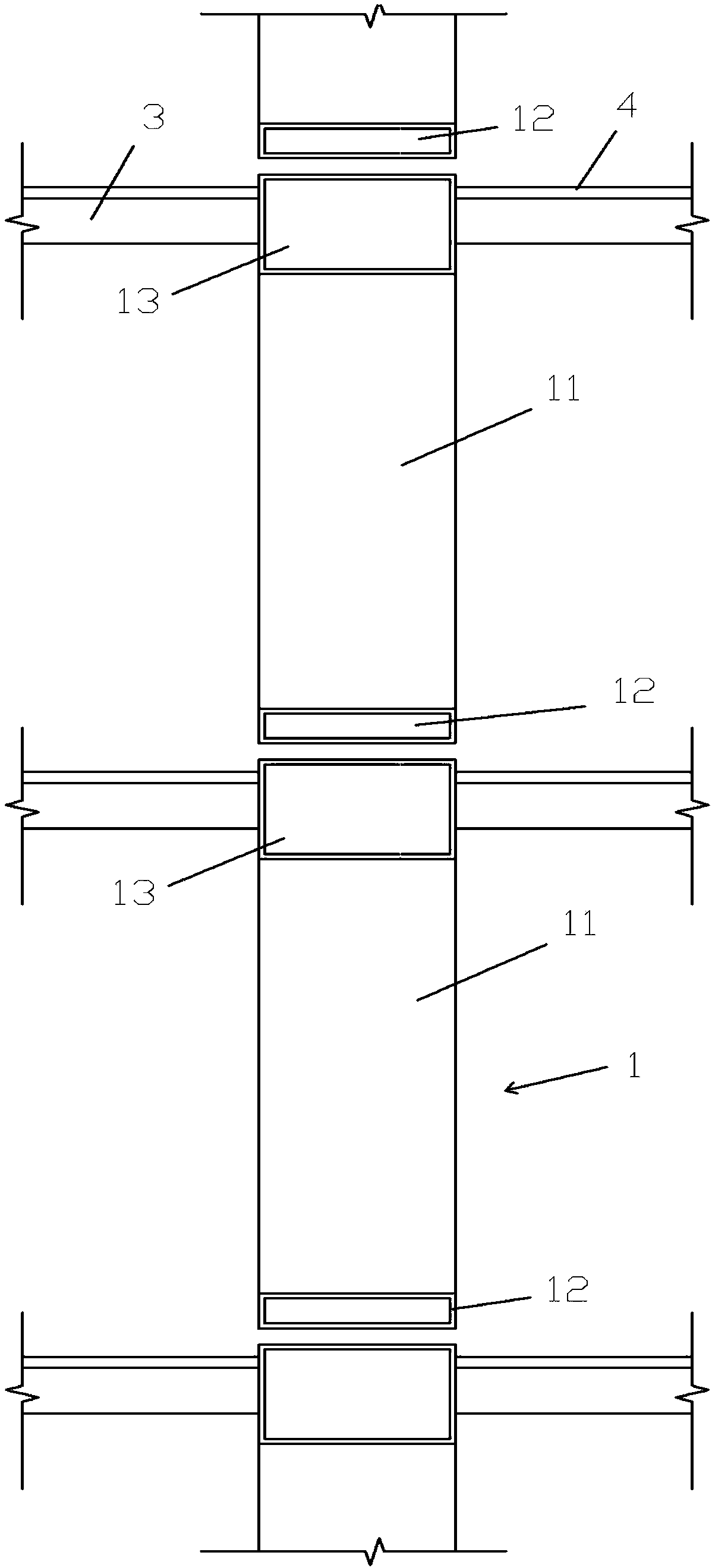
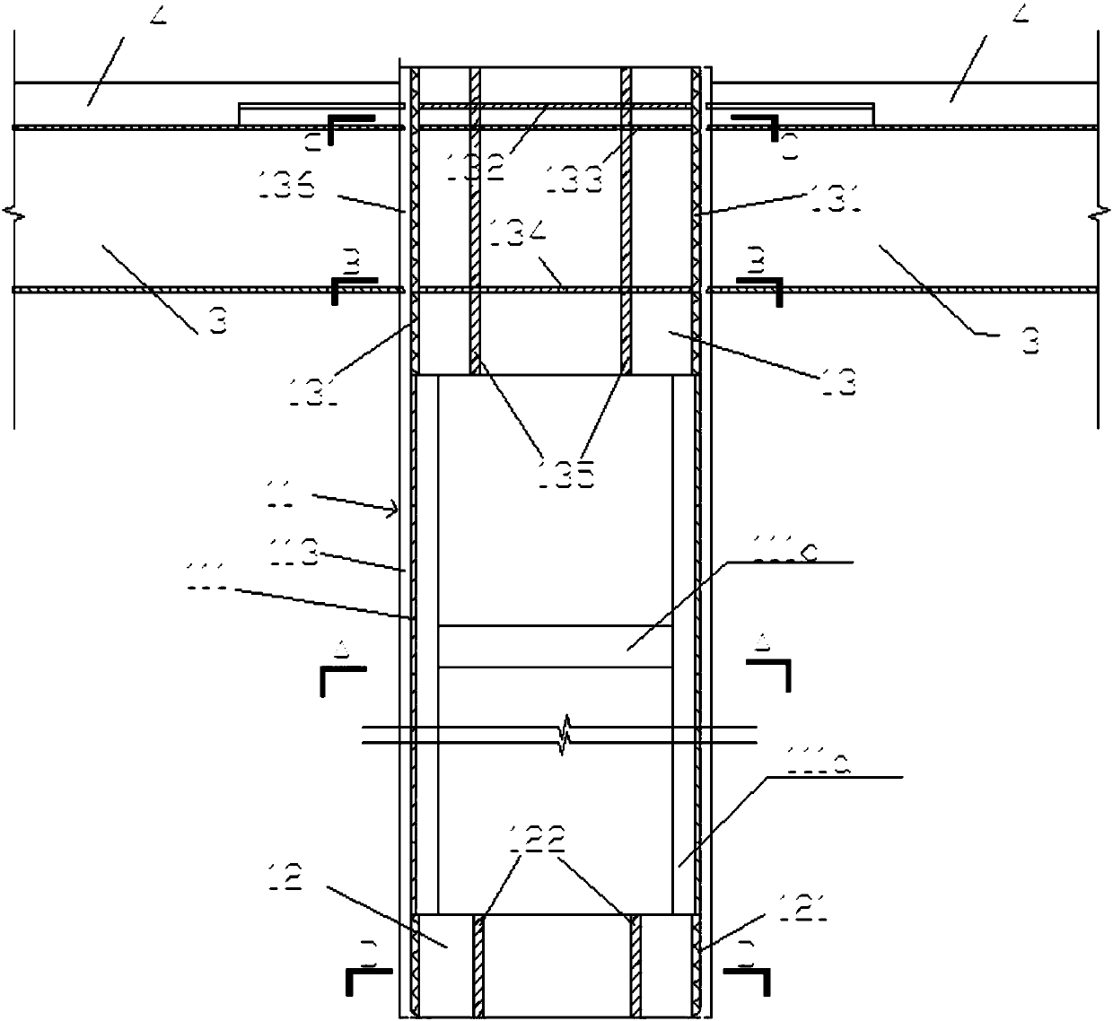
[0072] Figure 1 to Figure 12 The standard assembly section in the shown embodiment one is a square column.
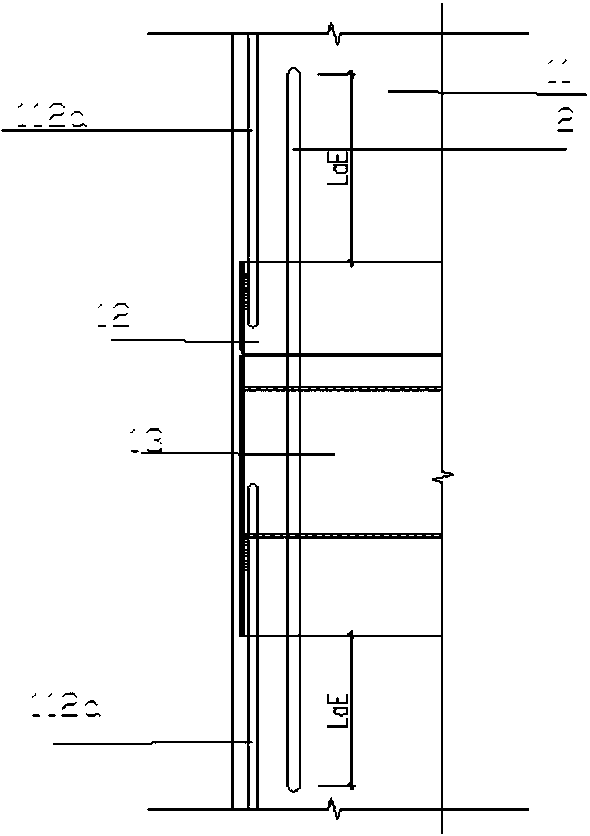
[0073] figure 1 It is a structural schematic diagram of the composite column of Embodiment 1 of the present invention, such as figure 1 As shown, the composite column of this embodiment is formed by splicing and fixing the upper and lower parts of the standard assembly section 1 assembled from prefabricated components and pouring in-situ concrete. The ends of two adjacent standard assembled sections 1 are welded and fixed, and are connected by several structural bars 2 anchored in the concrete, and the two ends of the structural bars 2 respectively extend into the single-layer section frame 11 ( mentioned below), such as figure 2 As shown, the length extending into the single-layer segmented frame 11 is at least LaE, and LaE is the seismic anchorage length, and the specific value of LaE can be obtained by looking up the table according to requirements.
[0074] ...
Embodiment 2
[0112] The standard assembly section in the second embodiment is a circular column.
[0113] Such as Figure 13 As shown, the single-layer segmented frame in Embodiment 2 is the same as Embodiment 1, and is also composed of a main steel frame 111, a finished plate 113 surrounding the main steel frame, and a reinforcement cage 112 welded in the main steel frame 111. . The column longitudinal bars 112a in the reinforcement cage 112 are arranged circumferentially along the inner wall of the main steel frame 111 to form a cylindrical shape corresponding to the inner profile of the main steel frame 111 .
[0114] In this embodiment, the main steel frame 111 includes steel hoops 111b, and four vertically arranged and cylindrical support plates 111c. The steel hoops 111b are connected to adjacent support plates 111c for shaping to form a steel frame. The support plate 111c is an arc-shaped plate, and the four support plates 111c are evenly distributed on the circumference of the cy...
Embodiment 3
[0121] The standard assembly section in the third embodiment is a special-shaped column.
[0122] Such as Figure 17 As shown, the single-layer segmented frame in the third embodiment is the same as the first embodiment, and is also composed of the main steel frame 111, the finished plate 113 surrounding the main steel frame, and the reinforcement cage 112 welded in the main steel frame 111. . The column longitudinal bars 112a in the reinforcement cage 112 are arranged circumferentially along the inner wall of the main steel frame 111 to form a columnar structure with a trapezoidal cross-section whose shape corresponds to the inner shape of the main steel frame 111 .
[0123] In this embodiment, the main body steel frame 111 includes a support plate 111c and a corner member 111a. Both the support plate 111c and the corner member 111a are arranged vertically. Between the two corner members 111a on the long side, a trapezoidal column structure is formed. The main steel frame 1...
PUM
 Abstract
Description
Claims
Application Information
 - R&D
- Intellectual Property
- Life Sciences
- Materials
- Tech Scout
- Unparalleled Data Quality
- Higher Quality Content
- 60% Fewer Hallucinations
Browse by: Latest US Patents, China's latest patents, Technical Efficacy Thesaurus, Application Domain, Technology Topic, Popular Technical Reports.
© 2025 PatSnap. All rights reserved.Legal|Privacy policy|Modern Slavery Act Transparency Statement|Sitemap|About US| Contact US: help@patsnap.com


