Air compressor oil-gas separation device and oil-gas separation method thereof

An air compressor and separation device technology, which is applied to the components of the pumping device for elastic fluids, mechanical equipment, machines/engines, etc., can solve the problems of no lubricating oil sealing effect, high cost, limited separation effect, etc. To achieve the effect of reducing the separation burden, improving the service life, improving the oil and gas separation efficiency and separation effect

Inactive Publication Date: 2018-01-09
烟台正祺科技有限公司
View PDF5 Cites 0 Cited by
  • Summary
  • Abstract
  • Description
  • Claims
  • Application Information

AI Technical Summary

Problems solved by technology

[0003] Existing electric air compression devices mainly include lubricated and non-lubricated. The non-lubricated electric compressor device has direct contact with parts and components without the protection of lubricating oil, resulting in fast wear of the compression mechanism and low service life. The sealing effect of oil-free lubricated electric air compression devices is generally low
[0004] Lubricated air compression devices mainly include rotary vane air compressors, screw air compressors and piston air compressors, but they all face the same problem, that is, the compressed air discharged from the air compression device usually contains lubricating oil, not only Causes waste of lubricating oil, but also causes damage to gas parts, such as corrosion of cylinder seals
In order to solve the above problems, the existing solution is to install an oil-gas separator on the air compression device to separate the compressed air. Only one oil-gas separator is used for oil-gas separation, not only the separation effect is limited, but also the life of the oil-gas separator is short and the cost is high.

Method used


Image

  • Air compressor oil-gas separation device and oil-gas separation method thereof
  • Air compressor oil-gas separation device and oil-gas separation method thereof

Examples


Embodiment Construction

[0029] Below in conjunction with accompanying drawing and embodiment the present invention will be further described:

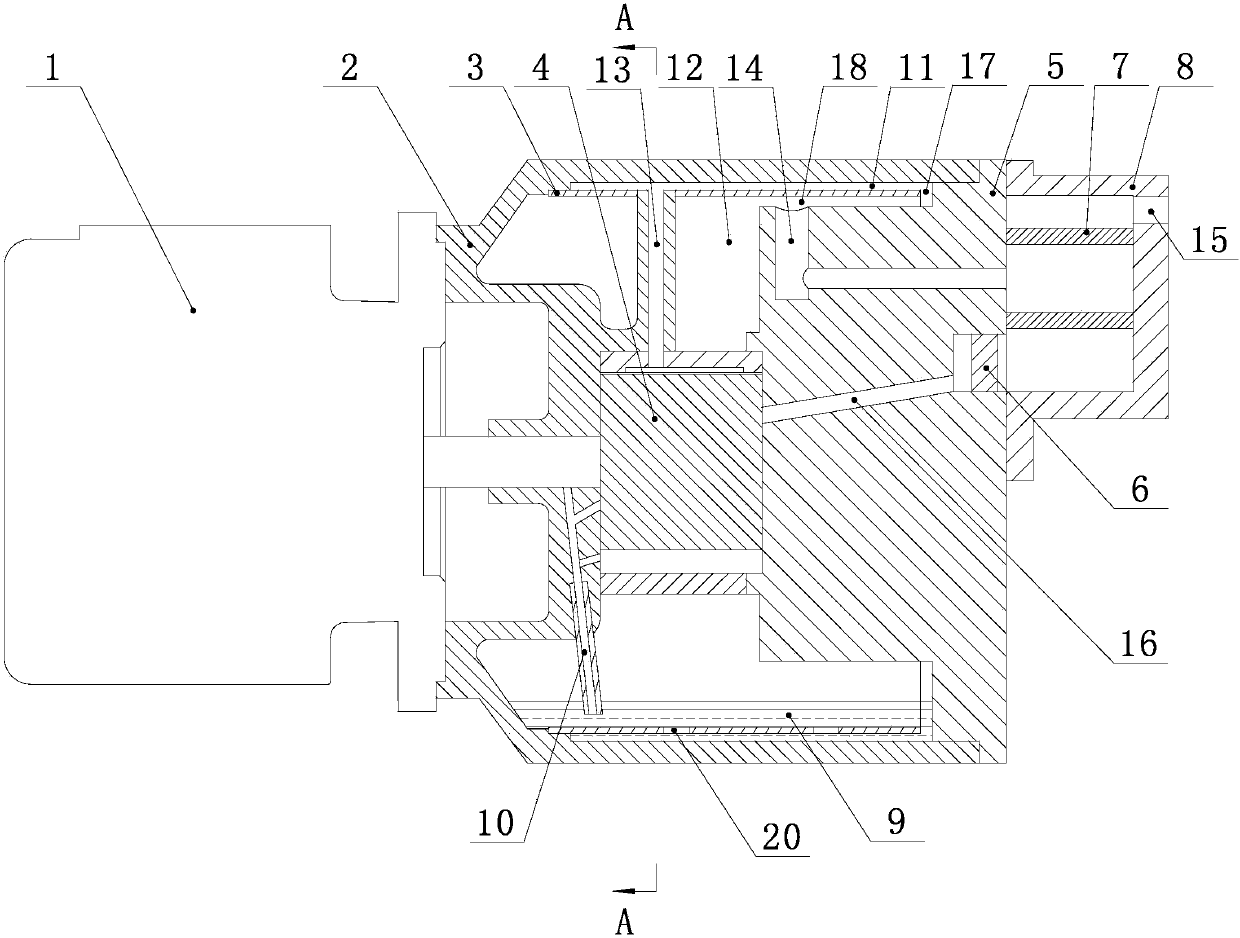
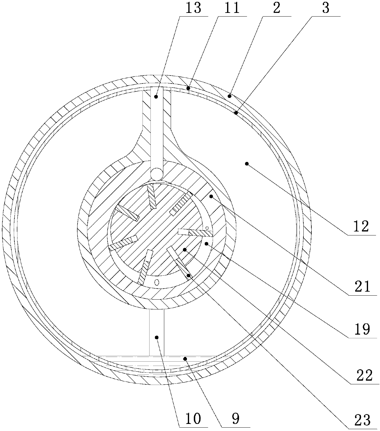
[0030] Such as Figures 1 to 2 As shown, an air compressor oil-gas separation device includes an oil-gas separation shell 2, one end of the oil-gas separation shell 2 is connected to the motor 1, and the other end is connected to the end cover 5, and the oil-gas separation shell 2 is provided with a spacer 3. A gap 17 is provided between the end of the spacer 3 and the end cover 5, a gap 18 is provided between the inner wall of the spacer 3 and the end cover 5, and an oil-gas separation chamber is provided between the spacer 3 and the oil-gas separation shell 2 11. There is also a compression device 4 inside the oil-gas separation shell 11. A pressure-holding chamber 12 is provided between the compression device 4 and the spacer 3. The oil-gas separation chamber 11 communicates with the pressure-holding chamber 12 through the gap 17 and the gap 18 in sequence...


PUM


Abstract

The invention discloses an oil-gas separation device of an air compressor. The device comprises an oil-gas separation shell; a spacing sleeve is arranged in the oil-gas separation shell; a gap is formed between the end part of the spacing sleeve and an end cover; an interval is formed between the inner wall of the spacing sleeve and the end cover; an oil-gas separation cavity is formed between the spacing sleeve and the oil-gas separation shell; a compression device is arranged in the oil-gas separation shell; a pressure keeping cavity is formed between the compression device and the spacing sleeve; the oil-gas separation cavity is communicated with the pressure keeping cavity through the gap and the interval in sequence; the compression device is communicated with the oil-gas separation cavity through an oil-gas separation exhaust pipe; an end cover exhaust pipe is arranged in the end cover; an inlet of the end cover exhaust pipe is communicated with the interval; an oil-gas separator shell is arranged on the outer side of the end cover; and an oil-gas separator is arranged in the oil-gas separator shell. The device improves the oil-gas separation efficiency and separation effect through layer-by-layer oil-gas separation, reduces the separation burden of the oil-gas separator, and prolongs the service life of the oil-gas separator.

Description

Technical field: [0001] The invention relates to the technical field of air compressor oil-gas separation, in particular to an air compressor oil-gas separation device and an oil-gas separation method thereof. Background technique: [0002] At present, in the fields of automobile manufacturing, processing centers and construction industries, many jobs are realized by pressure gas, which mainly comes from air compressors. With the extensive development and popularization of electrified equipment, electric air compressors It is also becoming more and more popular. [0003] Existing electric air compression devices mainly include lubricated and non-lubricated. The non-lubricated electric compressor device has direct contact with parts and components without the protection of lubricating oil, resulting in fast wear of the compression mechanism and low service life. The sealing effect of oil-free lubricated electric air compression devices is generally low. [0004] Lubricated ...

Claims


Application Information

Patent Timeline
Patent Type & Authority Patents(China)
IPC IPC(8): F04C29/02
CPCF04C29/026
Inventor 邢绍校
Owner 烟台正祺科技有限公司
Why Eureka
Try Eureka