Clutch release bearing device and motor vehicle equipped with such bearing

一种分离轴承、离合器的技术,应用在离合器、机械驱动离合器、轴承等方向,能够解决增加源自摩擦、减少使用寿命等问题,达到减小摩擦、减少污染、灰尘和颗粒量减少的效果

Active Publication Date: 2016-10-26
AB SKF
View PDF4 Cites 1 Cited by
  • Summary
  • Abstract
  • Description
  • Claims
  • Application Information

AI Technical Summary

Problems solved by technology

[0004] However, the contact between the clutch release bearing arrangement and the drive member creates friction, reducing the service life of the device and increasing contamination from friction, especially from metal particles

Method used


Image

  • Clutch release bearing device and motor vehicle equipped with such bearing
  • Clutch release bearing device and motor vehicle equipped with such bearing
  • Clutch release bearing device and motor vehicle equipped with such bearing

Examples


Embodiment Construction

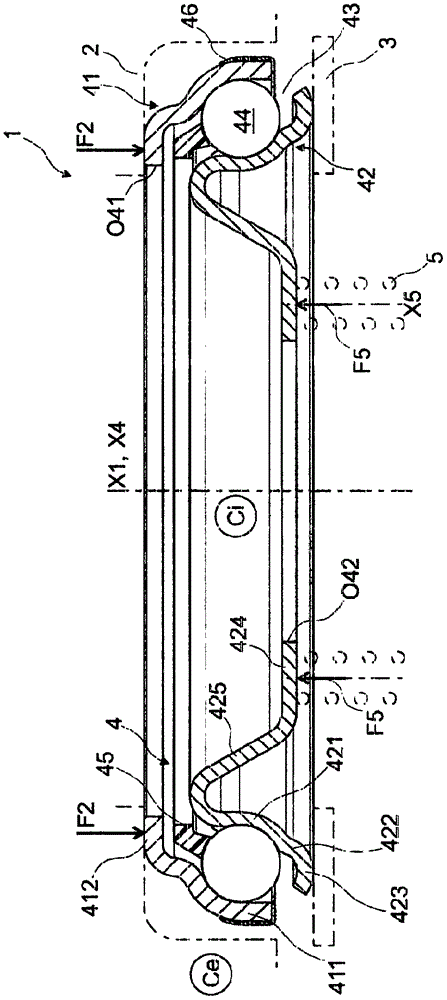
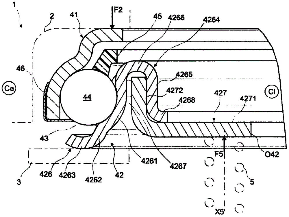
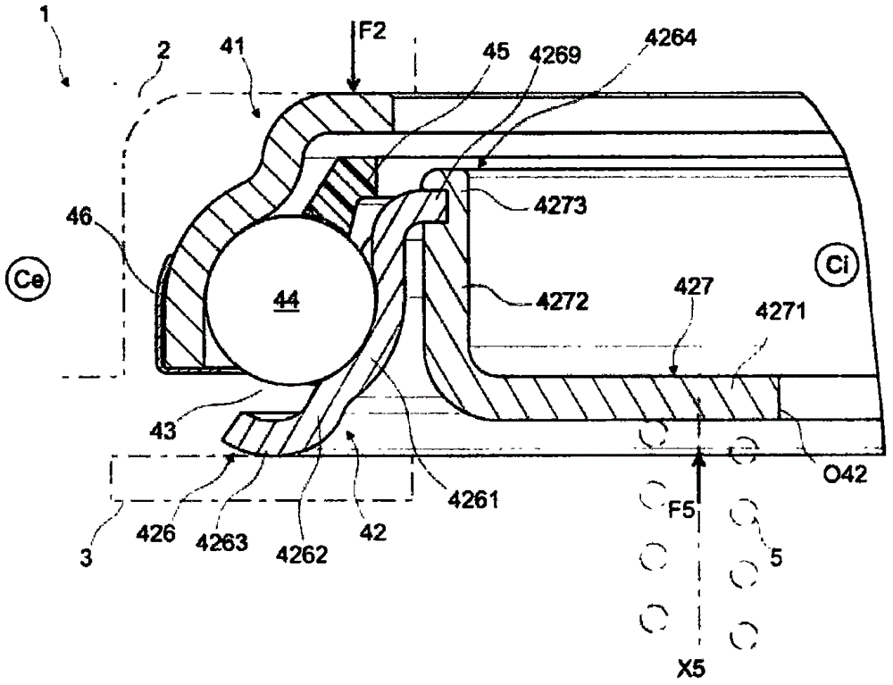
[0047] Figure 1-6 The clutch release bearing device 1 shown in is intended to be mounted on a motor vehicle in order to transmit an axial force F2 to a drive member 3 such as a pressure plate, which is exerted by a member 2 capable of translational movement, in figure 1 are shown only by dotted lines.

[0048] X1 represents the central axis of the clutch release bearing device 1 , and the rotation axis of the pressure plate coincides with X1 during normal operation of the device 1 .

[0049] In the following, for easier positioning of the bearing 1 in space, an inner side Ci corresponding to the main axis X1 is defined, which is the outer side Ce away from the axis X1 via the device 1 .

[0050] Furthermore, for the present and subsequent embodiments, the adjectives “axial” and “radial” and the adverb “axially” are defined with respect to the central axis X1 of the device 1 . The axial part or part is thus parallel to the axis X1, while the radial part or part is perpendicu...


PUM


Abstract

The invention relates to a motor vehicle clutch release bearing device (1) including a rolling bearing (4) that forms a member for transmitting an axial force (F2), having a rotating ring (41; 42) and a non-rotating ring (42; 41), between which a rolling chamber (43) for rolling elements (44) is defined. The rotating ring (42; 41) provides a first radial portion (423, 4263, 48; 4112) intended to come into contact with an actuating member (3) when a sufficient axial force (F2) is applied to the non-rotating ring (41; 42) by a member (2) that is able to move in translation, and a second radial portion (424, 4271; 4114) that is intended to bear against a spring (5), which exerts an axial force (F5) in the opposite direction to the axial force (F2) exerted by the member (2) that is able to move in translation, dedicated to preloading the rolling bearing in an opposite direction to the actuating member (3).

Description

technical field [0001] The present invention relates to a clutch release bearing arrangement for a motor vehicle to transmit axial force between a non-rotating part and a rotating part. Background technique [0002] In the automotive field it is known to use clutch release bearings driven by an element capable of translational movement to engage a manually controlled or automatically controlled gearbox. To this end, the clutch release bearing arrangement comprises a rolling bearing with rolling elements accommodated between a rotating ring and a non-rotating ring pressed by an element capable of translational movement. The device, in turn, includes a drive member integrated into the clutch, for example consisting of a pressure plate, intended to be driven axially by means of a rotating ring, said drive member then driving a rotating mechanical element to allow torque transmission and use of the gearbox . [0003] The device is formed to mount the clutch release bearing dev...

Claims


Application Information

Patent Timeline
Patent Type & Authority Applications(China)
IPC IPC(8): F16C19/16F16C33/62
CPCF16C19/16F16C33/62F16C2326/01F16D23/143F16C19/163F16C33/588F16C2361/43F16D23/147
Inventor B·阿诺尔特E·鲍德兹
Owner AB SKF
Why Eureka
Try Eureka