High pressure pneumatic valve

A pneumatic valve, pneumatic valve technology, applied in the direction of lift valve, valve details, valve device, etc., can solve the problems of high energy loss, high manufacturing cost, energy loss, etc., to achieve fast response speed, low manufacturing cost, and reduce energy loss. Effect

Active Publication Date: 2016-10-26
BRAY (TIANJIN) CONTROL SYST MFG CO LTD
View PDF5 Cites 3 Cited by
  • Summary
  • Abstract
  • Description
  • Claims
  • Application Information

AI Technical Summary

Problems solved by technology

[0002] In high-pressure valves, it is often necessary to use fast-response control fluid connection and closure valve devices. The response speed of the valve is one of the most important technical parameters of this type of valve, which has a great impact on the overall performance of the product. The existing fast-response High-pressure valves usually need to be adjusted to a suitable working pressure by a pressure-reducing valve before entering the pneumatic circuit. The decompression process is realized according to the principle of throttling and decompression. This working link will inevitably cause a large amount of energy loss, and the greater the decompression span, more energy loss
At the same time, the existing high-pressure valves have certain limitations in the realization of rapid response, and have defects such as complex structures and high manufacturing costs. Therefore, the existing high-pressure pneumatic valves need to be further improved and perfected.

Method used


Image

  • High pressure pneumatic valve
  • High pressure pneumatic valve

Examples


Embodiment Construction

[0024] It should be noted that, in the case of no conflict, the embodiments of the present invention and the features in the embodiments can be combined with each other.

[0025] In describing the present invention, it should be understood that the terms "center", "longitudinal", "transverse", "upper", "lower", "front", "rear", "left", "right", " The orientations or positional relationships indicated by "vertical", "horizontal", "top", "bottom", "inner" and "outer" are based on the orientations or positional relationships shown in the drawings, and are only for the convenience of describing the present invention and Simplified descriptions, rather than indicating or implying that the device or element referred to must have a particular orientation, be constructed and operate in a particular orientation, and thus should not be construed as limiting the invention. In addition, the terms "first", "second", etc. are used for descriptive purposes only, and should not be understood ...


PUM


Abstract

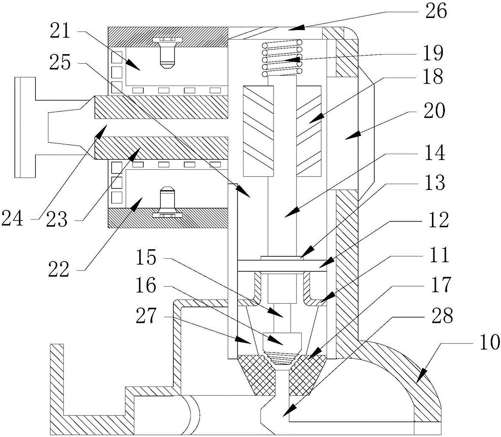
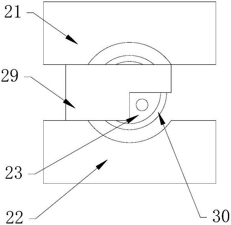
The invention provides a high pressure pneumatic valve. The high pressure pneumatic valve comprises a valve body, a valve cover, an air inlet port, an air inlet core, a valve core, a cone valve core, an air outlet valve sleeve and an air outlet port. The valve body and the valve cover form a sealed sealing air chamber. The air inlet port and the air inlet core are arranged on the upper end side of the sealing air chamber and a sealing baffle is arranged at the position, communicating with the sealing air chamber, of the air inlet core. A valve core shaft is arranged on the axis of the sealing air chamber. At least two impellers are arranged at the positions, corresponding to the air inlet port, of the valve core shaft and impeller magnets are arranged at the positions, corresponding to the impellers, of the valve body. The valve core shaft is fixedly connected with the cone valve core by a connecting shaft. The cone valve core comprises a cone-shaped bottom and the cone-shaped bottom is provided with a spiral boss. An air outlet valve sleeve, which is matched with the cone valve core, is arranged at the bottom of the sealing air chamber. The air outlet valve sleeve conducts the air outlet port to the sealing air chamber through an airflow through hole. The high pressure pneumatic valve has the following advantages of being fast in response speed, simple in structure, low in cost, wide in working pressure range and the like.

Description

technical field [0001] The invention belongs to the technical field of valves, in particular to a high-pressure pneumatic valve with quick response and self-locking function. Background technique [0002] In high-pressure valves, it is often necessary to use fast-response control fluid connection and closure valve devices. The response speed of the valve is one of the most important technical parameters of this type of valve, which has a great impact on the overall performance of the product. The existing fast-response High-pressure valves usually need to be adjusted to a suitable working pressure by a pressure-reducing valve before entering the pneumatic circuit. The decompression process is realized according to the principle of throttling and decompression. This working link will inevitably cause a large amount of energy loss, and the greater the decompression span, The more energy is lost. At the same time, the existing high-pressure valves have certain limitations in t...

Claims


Application Information

Patent Timeline
Patent Type & Authority Applications(China)
IPC IPC(8): F16K1/00F16K1/38F16K31/06
CPCF16K1/00F16K1/38F16K31/0655
Inventor 金峰华金铖磊
Owner BRAY (TIANJIN) CONTROL SYST MFG CO LTD
Why Eureka
Try Eureka