
Probe card

A probe card and signal needle technology, applied in the field of probe cards, can solve the problems of reducing test accuracy and so on

Inactive Publication Date: 2016-10-26
MPI CORP
View PDF7 Cites 2 Cited by
  • Summary
  • Abstract
  • Description
  • Claims
  • Application Information

AI Technical Summary

Problems solved by technology

However, when using a probe card to test multiple electronic components under test at the same time, if the power signals transmitted to each electronic object under test are inconsistent, in other words, if each electronic object under test is tested under different test conditions, Then it will affect the results detected by the electronic object to be tested, thereby reducing the accuracy of the test

Method used


Image

  • Probe card
  • Probe card
  • Probe card

Examples


Embodiment Construction

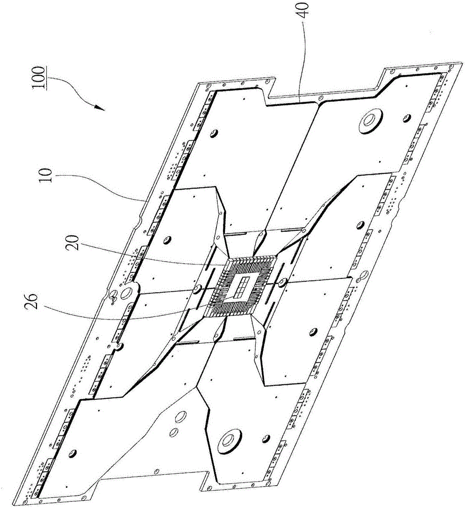
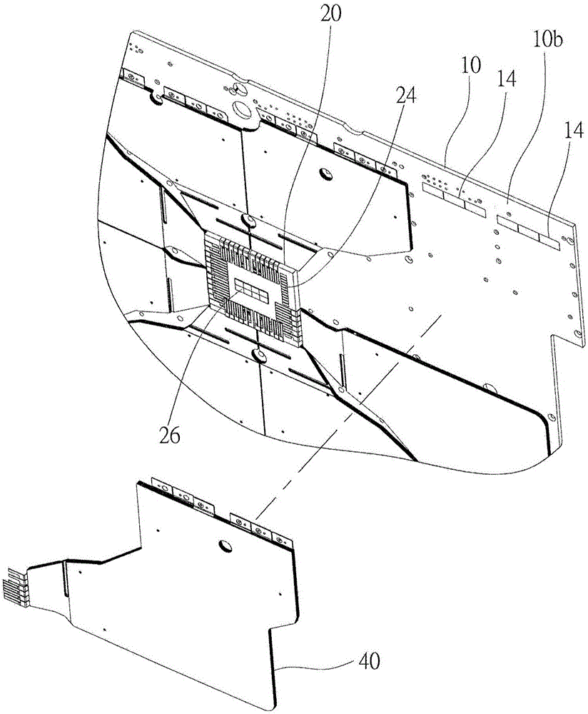
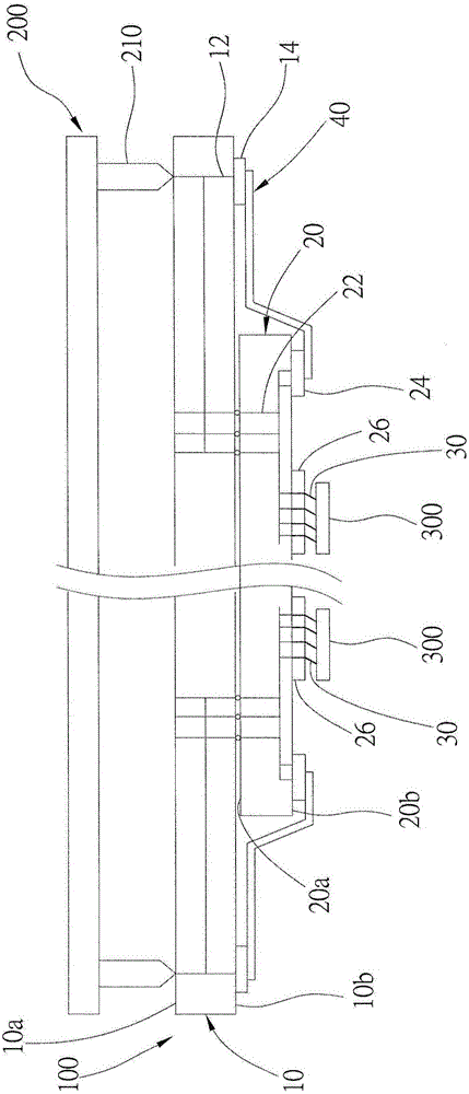
[0029] In order to explain the present invention more clearly, the preferred embodiments are described in detail below in conjunction with the accompanying drawings. See Figure 1 to Figure 3 Shown is a probe card 100 according to a preferred embodiment of the present invention. The probe card 100 is used to transmit power signals output from a plurality of power terminals 210 of a testing machine 200 to a plurality of electronic objects 300 to be tested. The power signal is used to supply power to the electronic object 300 to be tested for electrical testing. The probe card 100 includes a substrate 10, a carrier board 20, multiple signal pins 30 and multiple matching components 40. among them:

[0030] One side 10a of the substrate 10 is used for connecting with the inspection machine 200. In this embodiment, the substrate 10 is a multilayer printed circuit board, and a plurality of first power conductors 12 made of conductors are formed; each of the first power conductors 12...


PUM


Abstract

A probe card for transmitting power signals from a tester to two devices under test (DUTs) is provided, which includes two signal pins, two power conducting circuits, and at least a matching part. The signal pins are made of conductive materials, wherein one end of the signal pin contacts one of the DUTs. The two power conducting circuits are electrically connected to the two signal pins respectively to transmit the power signals to the DUTs. One of two ends of the power conducting circuits is connected to the signal pins; the other end of the power conducting circuits is electrically connected to the tester. The matching part is electrically connected to the power conducting circuit in parallel to lower a resistance of the power conducting circuit below a predetermined value, or to lower a percentage error of resistance of the power conducting circuit below a predetermined percentage error.

Description

Technical field [0001] The invention relates to a probe card, in particular to a probe card with consistent impedances of power lines. Background technique [0002] The method used to detect whether the electrical connection between the precision electronic components of the electronic product is reliable is to use a probe card as the transmission interface of the power signal between a testing machine and the electronic object under test. The electronic component under test usually receives a power signal from the testing machine to supply the power required by the electronic component under test. [0003] In addition, in order to improve the efficiency of the probe card for detecting the electronic components under test, using a set of probe cards to test multiple electronic components under test at the same time is one of the most effective detection methods at present. However, when using a probe card to test multiple electronic components under test at the same time, if the p...

Claims


Application Information

Patent Timeline
Patent Type & Authority Applications(China)
IPC IPC(8): G01R1/073
CPCG01R1/07314G01R31/31924G01R31/2889
Inventor 顾伟正赖俊良何志浩魏豪
Owner MPI CORP
Learn More