Unmanned plane automatic landing guiding method based on optical flow

A technology for automatic landing and unmanned aerial vehicles, which is applied in non-electric variable control, target-seeking control, instruments, etc., and can solve the problems of sound source time delay method environmental interference, unmanned aerial vehicle crashes, missing and other problems

Active Publication Date: 2016-10-26
NORTHWESTERN POLYTECHNICAL UNIV
View PDF3 Cites 31 Cited by
  • Summary
  • Abstract
  • Description
  • Claims
  • Application Information

AI Technical Summary

Problems solved by technology

The new requirements for the use of civilian drones such as the recovery of shooting equipment from tiny platforms (such as car roofs) and the fixed-point delivery of goods in the express delivery industry during dynamic tracking and shooting, all pose new challenges to the automatic landing technology of micro-UAVs.
[0003] The most commonly used solution based on GPS automatic landing at present, but this type of automatic landing technology based on GPS navigation all has some shortcomings: 1) the current civilian GPS positioning accuracy can only reach 10 meters, for some areas with complex terrain, such as buildings In dense urban centers, it is very likely that the drone will crash during low-altitude approach due to navigation errors; 2) GPS signals are greatly interfered by non-air media, and the error will increase in areas with many obstacles (such as forests) Even the signal is missing; 3) Professional-grade high-precision GPS equipment is expensive and economical
However, the source delay method is still subject to environmental interference

Method used


Image

  • Unmanned plane automatic landing guiding method based on optical flow
  • Unmanned plane automatic landing guiding method based on optical flow
  • Unmanned plane automatic landing guiding method based on optical flow

Examples


Embodiment Construction

[0073] Embodiments of the present invention are described in detail below, and the embodiments are exemplary and intended to explain the present invention, but should not be construed as limiting the present invention.

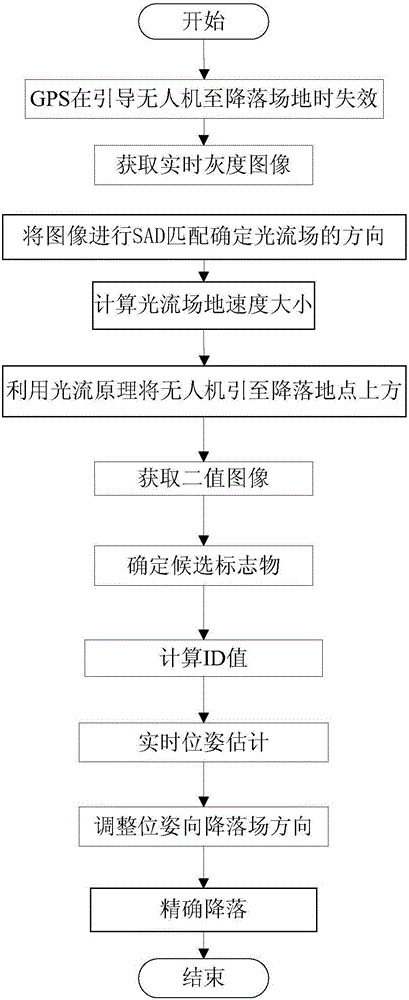
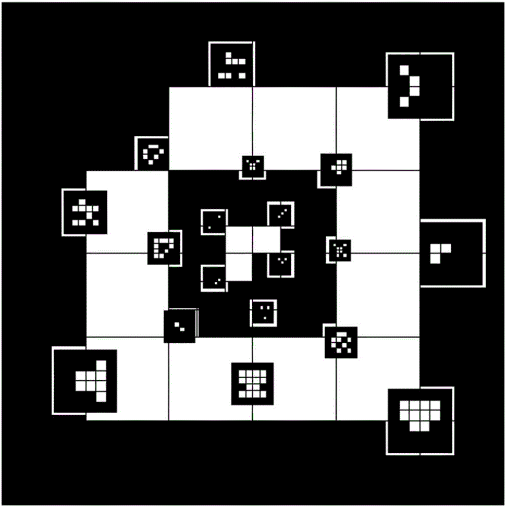
[0074] Such as figure 1 As shown, it shows that the present invention leads the UAV to the approximate range above the landing site, the GPS fails, uses the optical flow module to guide the UAV to move to the approximate range above the landing site, and the precise process of the drone's autonomous landing. Firstly, the GPS and optical flow modules are used for navigation and positioning to guide the drone to an approximate position a few meters above the landing site. The present invention takes a 6*6 (the landing site can be divided into a square area composed of N*N identical grid areas, called N*N markers) two-dimensional code marker scheme as the landing site as an example.

[0075] When there is GPS, use GPS navigation to guide the drone to a few meter...


PUM


Abstract

The invention provides an unmanned plane automatic landing guiding method based on an optical flow. In the process of landing, a marker is determined by processing the real-time image shot by the camera of an optical flow module, the position and attitude of the marker relative to an unmanned plane are estimated, the relative position and attitude information are sent to a flight controller to control the unmanned plane to gradually approach the landing target, and the full-autonomous landing of the unmanned plane can be ultimately achieved. Because the unmanned plane realizes the self-positioning in the autonomous flight and landing process by a downward viewing optical flow sensor, the visual positioning of itself can be completed without a GPS. And in the case of GPS failure, the auxiliary positioning can be carried out by means of the optical flow module, so that the unmanned plane can accurately find the landing site, and the reliability of the unmanned plane landing can be improved. The method is reasonable in design, can achieve accurate landing under different conditions, and is wide in applicability.

Description

technical field [0001] The invention relates to the field of autonomous navigation of unmanned aerial vehicles and robots, in particular to an optical flow-based automatic landing guidance method for unmanned aerial vehicles. Background technique [0002] In recent years, due to its small size, light weight, and good concealment, micro-UAVs have been widely used in various fields such as photography, monitoring, investigation, tracking, and mapping, and opened the era of UAV technology explosion. The new requirements for the use of civilian drones such as the recycling of shooting equipment by tiny platforms (such as car roofs) during dynamic tracking and shooting, and the fixed-point delivery of items in the express industry, all pose new challenges to the automatic landing technology of micro-UAVs. [0003] The most commonly used solution based on GPS automatic landing at present, but this type of automatic landing technology based on GPS navigation all has some shortcomin...

Claims


Application Information

Patent Timeline
Patent Type & Authority Applications(China)
IPC IPC(8): G05D1/12G05D1/08G05D1/10
CPCG05D1/0808G05D1/101G05D1/12
Inventor 布树辉杨君赵勇张臻炜
Owner NORTHWESTERN POLYTECHNICAL UNIV
Why Eureka
Try Eureka