
Control method of vacuum tap changer

A technology of tap changer and control method, which is applied to electric switches, high-voltage/high-current switches, high-voltage air circuit breakers, etc. And static contacts, the implementation effect is unsatisfactory and other problems, to achieve the effect of eliminating the impact of service life, not easy to damage, and long service life

Active Publication Date: 2018-02-27
宁波安德奥电力设备有限公司
View PDF5 Cites 0 Cited by
  • Summary
  • Abstract
  • Description
  • Claims
  • Application Information

AI Technical Summary

Problems solved by technology

[0008] However, the content described in the claims of the patent, the description and the embodiment structure described in the description do not have any precise control over the opening and closing time of the vacuum tube, and the positional relationship between the active contact and the driven contact. Specifically, when the invention is actually implemented, it is still impossible to accurately ensure that when the moving contact contacts the static contact, the voltage difference between the moving contact and the static contact has been lost, that is, it is impossible to know the operating time and time of the two vacuum tubes. The corresponding relationship between the contact time of the moving contact and the static contact, so this product still cannot accurately complete the arc extinguishing between the moving contact and the static contact, and the implementation effect is not satisfactory, and it cannot reach the requirements described in the patent. good technical effect

Method used


Image

  • Control method of vacuum tap changer
  • Control method of vacuum tap changer
  • Control method of vacuum tap changer

Examples


Embodiment Construction

[0041] Embodiments of the invention will be further described below in conjunction with the accompanying drawings.

[0042] The method described in the present invention is used for vacuum tap changers.

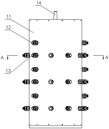
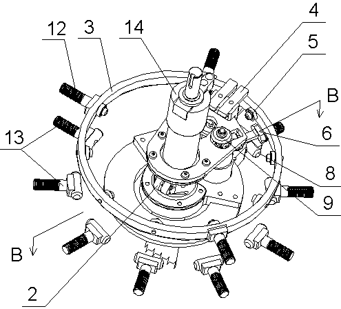
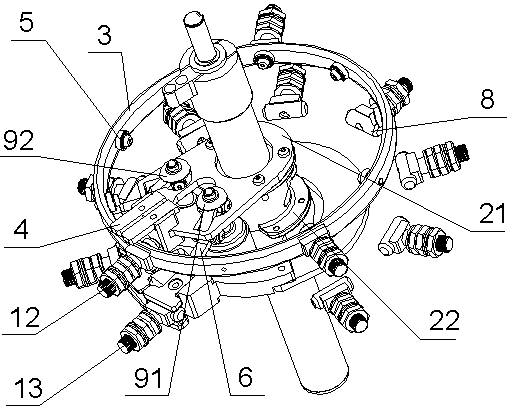
[0043] The shell of the vacuum tap changer is an insulating cylinder 11, and a multi-layer mounting bracket 2 is fixedly installed on the main shaft 14 in the center of the insulating cylinder. Each layer of mounting bracket is divided into a contact bracket 21 and a moving contact bracket 22. The contact piece 4 is in continuous contact with the conductive ring 3 arranged on the inner wall of the insulating cylinder, and the active contact and the transition contact are arranged on the moving contact bracket, which are all matched with the static contacts arranged at intervals on the inner wall of the insulating cylinder; the vacuum tube has two , the main vacuum tube and the active contact are connected in series, and the transition vacuum tube, the transition contact and t...


PUM


Abstract

A control method for a vacuum tapping switch is successively performed through eight steps. After a main moving contact and an auxiliary moving contact are guaranteed to accurately contact static contacts, corresponding vacuum switches are connected then; and before the main moving contact and the auxiliary moving contact are separated from the static contacts, the corresponding vacuum switches are disconnected in advance, a position where an electric arc may occur is moved into a vacuum tube, and a gear shift is completed. The method has a substantial arc-extinguishing effect and prolongs the service life of the tapping switch.

Description

technical field [0001] The invention relates to a control method for a controller of electric equipment, in particular to a control method for a vacuum tap changer used to ensure accurate arc extinguishing of a vacuum tube under load or no-load conditions. Background technique [0002] For ordinary on-load tap-changers, when the gear is switched, it must be ensured that the active contact cannot be cut off when the active contact moves away from the previous gear and moves to the next gear, and the state of electrical conduction must always be maintained. The static contacts of two different gears obviously cannot be conducted with each other, otherwise a short circuit will occur and the meaning of shifting will be lost. In order to solve this problem, the common on-load tap-changer adds a transition contact next to the active contact, and a shift resistor is connected in series on the transition contact. When the active contact leaves the original gear, the transition conta...

Claims


Application Information

Patent Timeline
Patent Type & Authority Patents(China)
IPC IPC(8): H01H33/664H01F29/04
CPCH01F29/04H01H33/664
Inventor 史伟峰陆琛杰
Owner 宁波安德奥电力设备有限公司
Learn More