An improved cell module
A cell module and cell technology, applied in circuits, electrical components, battery pack components, etc., can solve the problems of difficulty in maintaining cell consistency, shortening cell replacement cycles, and increasing maintenance costs, reducing maintenance costs. Cost, easy operation, and firm fixation
Active Publication Date: 2018-06-05
SYST ELECTRONICS TECH ZHENJIANG CO LTD +1
View PDF7 Cites 0 Cited by
- Summary
- Abstract
- Description
- Claims
- Application Information
AI Technical Summary
Problems solved by technology
[0002] After the existing module is assembled, the tabs are all on one side of the module. If the module is discharged at this time, the discharge path of the cells close to the tabs is relatively short compared to the cells far away from the tabs. The required power is the same. Therefore, the battery cells farther away from the tabs will emit more power than the batteries close to the tabs, and the loss will be greater. Consistency is difficult to maintain, resulting in shorter battery replacement cycles and relatively higher maintenance costs
Method used
View moreImage
Smart ImageViewing Examples
Examples
Embodiment Construction
[0015] In order to make the technical solution of the present invention clearer, the present invention will be further described below in conjunction with the accompanying drawings. Any solution obtained by equivalent replacement and conventional reasoning of the technical features of the technical solution of the present invention falls within the protection scope of the present invention.
Login to View More PUM
 Abstract
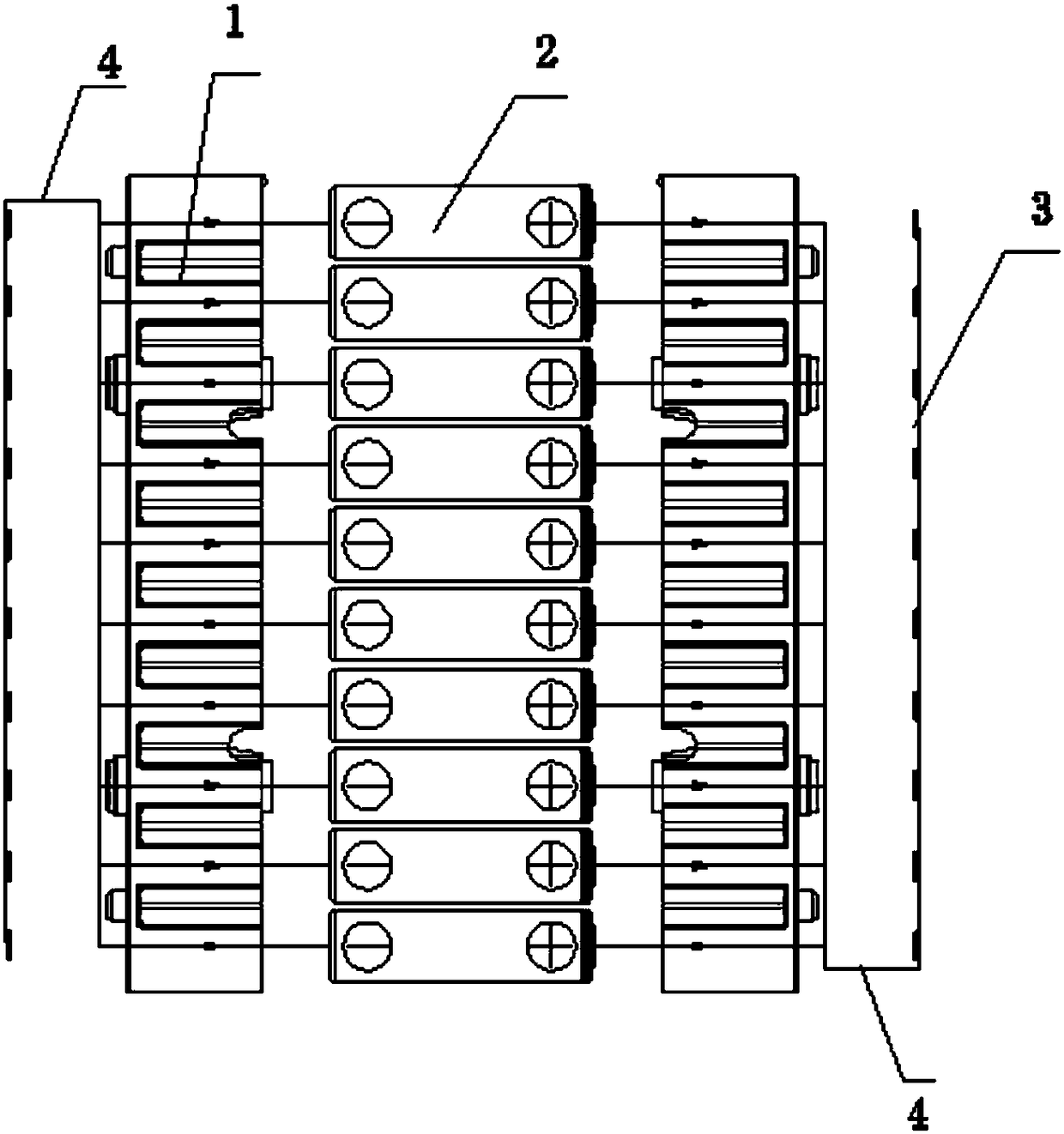
The invention relates to an improved cell module, which includes a cell bracket, a cell and a nickel-plated steel sheet, the number of the cell bracket is two, the cells are arranged between the cell brackets, and the nickel-plated steel There are tabs on the chip, and the number of nickel-plated steel sheets is two. The tabs of the two nickel-plated steel sheets are fixed on the cell support in reverse, so that the length of the current path of the cell is consistent, and the replacement cycle of the cell is extended. Reduce maintenance costs, and at the same time, change the combination of battery modules and improve work efficiency.
Description
technical field [0001] The invention relates to a battery module, in particular to an improved battery module. Background technique [0002] After the existing module is assembled, the tabs are all on one side of the module. If the module is discharged at this time, the discharge path of the cells close to the tabs is relatively short compared to the cells far away from the tabs. The required power is the same. Therefore, the battery cells farther away from the tabs will emit more power than the batteries close to the tabs, and the loss will be greater. Consistency is difficult to maintain, resulting in shorter battery replacement cycles and relatively higher maintenance costs. Contents of the invention [0003] In view of the above problems, the present invention proposes an improved battery module, which makes the length of the current path of the battery consistent, prolongs the replacement cycle of the battery, reduces maintenance costs, and at the same time changes t...
Claims
Login to View More Application Information
Patent Timeline
 Patent Type & Authority Patents(China)
IPC IPC(8): H01M2/10H01M2/20H01M2/26H01M50/204H01M50/531
CPCH01M50/20H01M50/502H01M50/531Y02E60/10
Inventor 史云福陈星常昊
Owner SYST ELECTRONICS TECH ZHENJIANG CO LTD
Features
- R&D
- Intellectual Property
- Life Sciences
- Materials
- Tech Scout
- Unparalleled Data Quality
- Higher Quality Content
- 60% Fewer Hallucinations
Learn More Browse by: Latest US Patents, China's latest patents, Technical Efficacy Thesaurus, Application Domain, Technology Topic, Popular Technical Reports.
© 2025 PatSnap. All rights reserved.Legal|Privacy policy|Modern Slavery Act Transparency Statement|Sitemap|About US| Contact US: help@patsnap.com


