Antenna module and electronic equipment

An antenna module and electronic equipment technology, applied to antennas, branch equipment, loop antennas, etc., can solve the problems of reducing antenna headroom, reducing antenna performance, affecting antenna radiation and receiving signals, and improving performance and bandwidth. Increase the headroom and avoid the effect of shielding the antenna

Inactive Publication Date: 2016-10-26
BEIJING XIAOMI MOBILE SOFTWARE CO LTD
View PDF6 Cites 29 Cited by
  • Summary
  • Abstract
  • Description
  • Claims
  • Application Information

AI Technical Summary

Problems solved by technology

[0002] With the increasing number of metal elements on the body of smartphones, all-metal shells have gradually become the mainstream, and the increase in metal a

Method used


Image

  • Antenna module and electronic equipment
  • Antenna module and electronic equipment
  • Antenna module and electronic equipment

Examples


Embodiment Construction

[0031] Reference will now be made in detail to the exemplary embodiments, examples of which are illustrated in the accompanying drawings. When the following description refers to the accompanying drawings, the same numerals in different drawings refer to the same or similar elements unless otherwise indicated. The implementations described in the following exemplary examples do not represent all implementations consistent with the present invention. Rather, they are merely examples of apparatuses and methods consistent with aspects of the invention as recited in the appended claims.

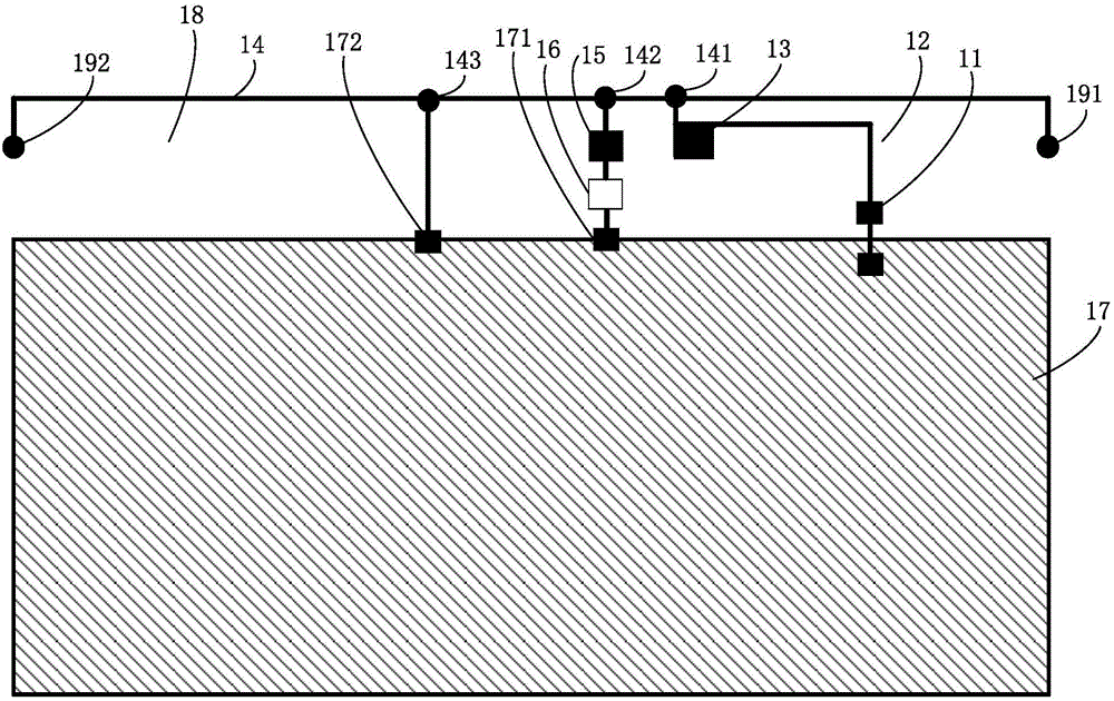
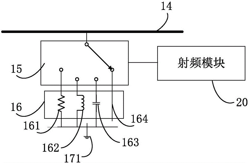
[0032] figure 1 is a schematic structural diagram of an antenna module shown according to an exemplary embodiment, figure 2 yes figure 1 Schematic diagram of the structure of the single-pole multi-throw switch in the illustrated embodiment; the antenna module can be applied to electronic devices (for example: smart phones, tablet computers) that need to receive or send signals through antenna...


PUM

PropertyMeasurementUnit
Capacitanceaaaaaaaaaa

Abstract

The invention discloses an antenna module and electronic equipment. The antenna module comprises a feed point, a capacitor, a metal sheet, a metal frame, a single-pole multi-throw switch, a capacitance-resistance sensitive component, a first grounding point and a second grounding point, wherein the feed point is electrically connected with an RF module of the electronic equipment and connected to the metal sheet via the capacitor, the metal sheet is electrically connected to a first contact point of the metal frame, a slit is formed between the metal frame and a metal casing of the electronic equipment, one end of the capacitance-resistance sensitive component is electrically connected to the first grounding point, the other end of the capacitance-resistance sensitive component is electrically connected to a second contact point of the metal frame via the single-pole multi-throw switch, the first and second grounding points are both arranged on the metal casing, and the second grounding point is electrically connected to a third contact point of the metal frame. According to technical schemes of the invention, performance and bandwidth of the antenna module are improved.

Description

technical field [0001] The present disclosure relates to the field of communication technologies, and in particular to an antenna module and electronic equipment. Background technique [0002] With the increasing number of metal elements on the body of smartphones, all-metal shells have gradually become the mainstream, and the increase in metal area will lead to a decrease in the headroom of the antenna, affecting the antenna's external radiation and receiving signals, and reducing the performance of the antenna. Contents of the invention [0003] In order to overcome the problems existing in the related technologies, the embodiments of the present disclosure provide an antenna module and electronic equipment to improve the performance of the antenna. [0004] According to the first aspect of an embodiment of the present disclosure, there is provided an antenna module, including: a feed point, a capacitor, a metal sheet, a metal frame, a single-pole multi-throw switch, a r...

Claims


Application Information

Patent Timeline
IPC IPC(8): H01Q1/24H01Q1/48H01Q5/10H01Q7/00H01Q23/00H04M1/02G06F1/16
CPCH01Q1/24G06F1/1613H01Q1/242H01Q1/48H01Q5/10H01Q7/00H01Q23/00H04M1/0202
Inventor 王霖川薛宗林熊晓峰
Owner BEIJING XIAOMI MOBILE SOFTWARE CO LTD
Why Eureka
Try Eureka