
High-power microwave dense-slot waveguide antenna

A high-power microwave and slot waveguide technology, applied in slot antennas, circuits, etc., can solve the problems of low compactness, low power capacity, and small number of slots, and achieve high power capacity, reduced equivalent resistance, and high radiation efficiency Effect

Active Publication Date: 2016-10-26
NAT UNIV OF DEFENSE TECH
View PDF6 Cites 17 Cited by
  • Summary
  • Abstract
  • Description
  • Claims
  • Application Information

AI Technical Summary

Problems solved by technology

[0004] The technical problem to be solved by the present invention is to overcome the disadvantages of low compactness and low power capacity caused by the small number of slots per unit length of the existing slot waveguide antenna, and provide a compact structure and high power capacity (GW level) High Power Microwave Dense Slot Waveguide Antenna

Method used


Image

  • High-power microwave dense-slot waveguide antenna
  • High-power microwave dense-slot waveguide antenna
  • High-power microwave dense-slot waveguide antenna

Examples


Embodiment Construction

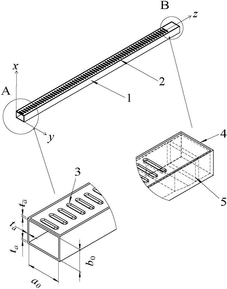
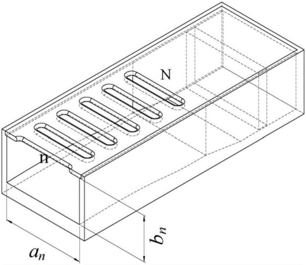
[0028] Such as Figure 1~4 As shown, the high-power microwave densely-covered slot waveguide antenna of the present invention is composed of a variable-section rectangular slot waveguide 1 and a thin absorbing load 5 . A thin absorbing load 5 is placed at the end of the variable cross-section rectangular slot waveguide 1 .

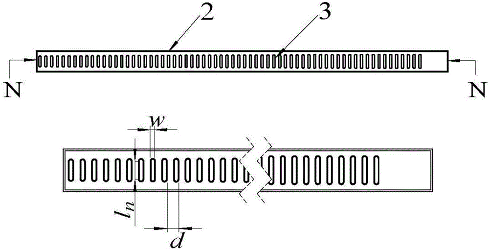
[0029]The cross-section of the inner cavity of the variable-section rectangular slot waveguide 1 is rectangular. One end of the variable-section rectangular slot waveguide 1 is an open input port, and the other end is a closed structure, which is closed by a metal baffle 4 . There are N slots 3 on one wide side of the variable-section rectangular slot waveguide 1, and the wide side with N slots is called the slot array interface 2, and the metal wall thickness of the slot array interface 2 is t a , the length direction of the slot is perpendicular to the axis of the waveguide, the width of the slot is w, and the length of the nth (n=1,2,3,...,N) slot is ...


PUM


Abstract

The invention relates to the field of high-power microwave technologies, in particular to a high-power microwave dense-slot waveguide antenna. Specific to the technical problem that an existing high-power microwave antenna with a low compactness degree cannot be applied to certain environments, the invention provides a high-power microwave waveguide slot antenna which is compact in structure and has relatively high power capacity and an arraying prospect. According to the characteristics of a large number of slots within a unit length of the waveguide slot antenna and relatively low coupling power allocated to the slots, relatively high power capacity is realized. Meanwhile, a relatively low antenna is designed according to the characteristics that the slots are formed in wide edges and waveguide narrow edges can be relatively small, so that actual applications are satisfied. Through adoption of the high-power microwave dense-slot waveguide antenna, the defects of low power capacity and relatively large size in a conventional waveguide slot antenna can be overcome, and an effective technical scheme is provided for projects.

Description

technical field [0001] The invention relates to an antenna in the technical field of high-power microwaves, in particular to a slot waveguide antenna with compact structure and high power capacity. Background technique [0002] High-power microwave specifically refers to electromagnetic waves with a peak power greater than 100MW and a frequency between 1 and 100GHz. The rapid development of related disciplines and the attractive prospects of many fields have attracted widespread attention and extensive research in many countries. As the terminal of the high-power microwave system, the antenna is an important component to realize the effective directional radiation of microwave. As the requirements of high-power microwave systems are getting higher and higher, conventional antennas can no longer meet the needs of high-power microwave applications. Transmitting antennas with compact structure, high power capacity, and strong environmental adaptability have become a development...

Claims


Application Information

Patent Timeline
Patent Type & Authority Applications(China)
IPC IPC(8): H01Q13/18
CPCH01Q13/18
Inventor 袁成卫王明阳张强孙云飞冯加怀
Owner NAT UNIV OF DEFENSE TECH
Learn More