Automatic charging control device and charging method for unmanned aerial vehicle

An automatic charging and control device technology, which is applied to charging stations, circuit devices, battery circuit devices and other directions for charging mobile devices, can solve the problems of inconvenient charging, low charging labor efficiency, and insufficient battery life, so as to improve comfort, The effect of avoiding short circuit and improving labor efficiency

Active Publication Date: 2016-10-26
青岛海盾雷达声纳工程技术有限公司
View PDF5 Cites 12 Cited by
  • Summary
  • Abstract
  • Description
  • Claims
  • Application Information

AI Technical Summary

Problems solved by technology

[0005] Aiming at the problems of insufficient battery life, inconvenient charging, and low manual efficiency of charging for drones, the present invention provides an automatic charging control device and charging method for drones, which can automatically charge the battery on-site when the drone is docked , no need or reduce the frequency of removing the battery from the drone and using a dedicated charger

Method used


Image

  • Automatic charging control device and charging method for unmanned aerial vehicle
  • Automatic charging control device and charging method for unmanned aerial vehicle
  • Automatic charging control device and charging method for unmanned aerial vehicle

Examples


Embodiment 1

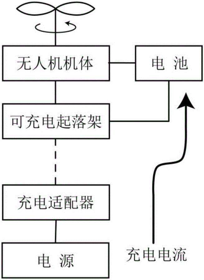
[0034] see image 3 , the invention comprises a rechargeable undercarriage (1), a charging adapter (2) and a power supply (3), and a cable (4) is provided between the charging adapter (2) and the power supply (3) to realize electrical connection.

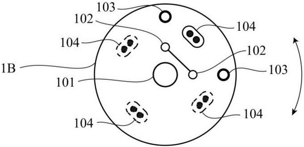
[0035] The rechargeable landing gear (1) includes a bracket (1A), a first electromechanical connector (1B), a charging accessory (1C), and a charging cable (1D); the bracket (1A) includes 4 upright curved supports, and the bracket ( 1A) The upper end has a screw hole for connecting the drone body, and each support (1A) has a first electromechanical connector (1B) at the lower end; the first electromechanical connector (1B) is a circular connector, and the connection method It is a pressure light touch connection; the charging accessory (1C) is an energy coupler during wireless charging, and a current limiting filter or current balancer during wired charging. Figure 5 It is the A-A sectional view of support (1A). In this example, ...

Embodiment 2

[0039] see Figure 4 , the invention comprises a rechargeable undercarriage (1), a charging adapter (2) and a power supply (3), and a cable (4) is provided between the charging adapter (2) and the power supply (3) to realize electrical connection.

[0040] The rechargeable landing gear (1) includes a bracket (1A), a first electromechanical connector (1B), a charging accessory (1C), and a charging cable (1D); the bracket (1A) includes two supports in the form of cross bars, and the bracket ( 1A) There are screw holes connecting the drone body at the upper end, and there is a first electromechanical connector (1B) on the cross bar at the lower end of each bracket (1A); the first electromechanical connector (1B) is a rectangular electrical connection The connection method is pressure light touch connection; the charging accessory (1C) is an energy coupler during wireless charging, and a current-limiting filter or current balancer during wired charging. Figure 5 It is the A-A se...


PUM


Abstract

The invention belongs to the field of charging control technology, and provides an automatic charging control device and a charging method for an unmanned aerial vehicle. The automatic charging control device comprises a rechargeable undercarriage, a charging adapter and a power supply. The automatic charging control device is mainly and technologically characterized in that the undercarriage with a charging function is utilized; an electromechanical connector with polarity adaption capability is utilized; and through automatic control of a charging control board, an in-position charging technical solution for the battery of the unmanned aerial vehicle is realized. The automatic charging control device and the charging method can be widely applied on an unmanned aerial vehicle landing device or a charging station.

Description

technical field [0001] The invention belongs to the technical field of charging control, and in particular relates to an automatic charging control device and a charging method for an unmanned aerial vehicle. Background technique [0002] In recent years, the application of drones in civil, police, military and other fields has developed rapidly. Small drones powered by batteries dominate the market because batteries are a clean energy source that emits no pollution and is easy to recycle. However, battery life has always been an important bottleneck in the application of drones. Usually, drones need to return to the ground to replace the batteries after flying in the air for 30 minutes, so that they can continue to perform flight missions. When performing critical tasks, the staff needs to carry multiple batteries, replace the batteries of the drones in turn, or use multiple drones to take off alternately to ensure the execution of continuous tasks. Whatever the case, the...

Claims


Application Information

Patent Timeline
Patent Type & Authority Applications(China)
IPC IPC(8): H02J7/00H02J50/00B64D27/24
CPCB64D27/24H02J5/005H02J7/0026H02J7/0027H02J7/0036H02J7/0048H02J7/025
Inventor 向志毅
Owner 青岛海盾雷达声纳工程技术有限公司
Why Eureka
Try Eureka