Magnetic coupling and mounting method thereof

A technology of magnetic coupling and installation method, which is applied in the direction of permanent magnet clutch/brake, electromechanical device, electric brake/clutch, etc., can solve the problem that the coaxiality of two permanent magnet rotors is difficult to guarantee, and achieve light weight and structure Compact and guarantee the effect of coaxiality

Active Publication Date: 2016-10-26
JIANGSU MAGNET VALLEY TECH
View PDF9 Cites 4 Cited by
  • Summary
  • Abstract
  • Description
  • Claims
  • Application Information

AI Technical Summary

Problems solved by technology

[0005] Therefore, the technical problem to be solved by the present invention is to firstly install the drive shaft and the load shaft with the inner permanent magnet rotor and the outer permanent magnet rotor respectively in order to overcome the prior art, and then install and combine the two permanent magnet rotors on site for easy adsorption and The defect that the coaxiality is difficult to guarantee when the two permanent magnet rotors are installed

Method used


Image

  • Magnetic coupling and mounting method thereof
  • Magnetic coupling and mounting method thereof

Examples


Embodiment 1

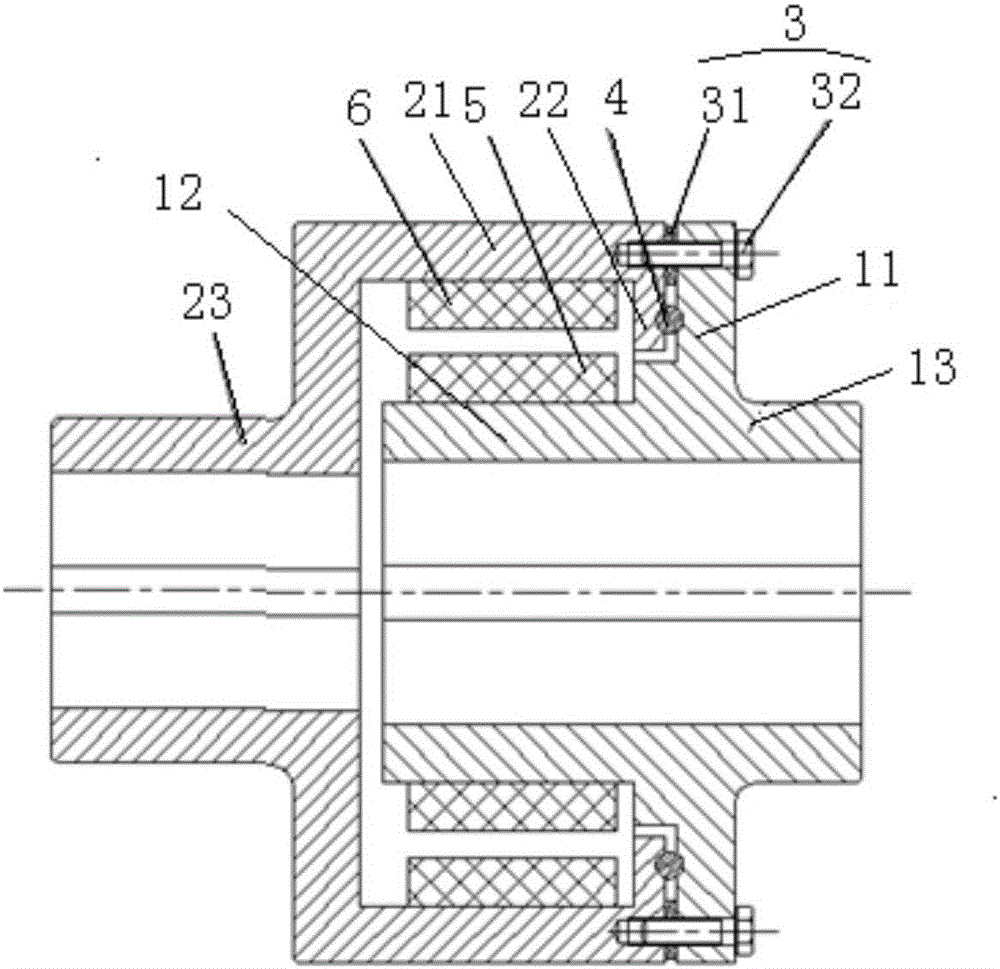
[0025] This embodiment provides a magnetic coupling, such as figure 1 shown, including:

[0026] The inner permanent magnet rotor includes an inner permanent magnet 5 and an inner cylinder part 12 for carrying the inner permanent magnet 5, and an annular flange 11 is provided on the outer wall of one end surface of the inner cylinder part 12;

[0027] The outer permanent magnet rotor includes an outer permanent magnet 6 and an outer cylinder part 21 for carrying the outer permanent magnet 6, the outer cylinder part 21 sleeves the inner cylinder part 12 and is away from the annular flange On the 11 side, there is an air gap between the inner permanent magnet 5 and the outer permanent magnet 6 and the magnetic poles are correspondingly matched;

[0028] The positioning connectors 3 are set to be several evenly arranged around the axis of the coupling, and are detachably connected to the end surface of the outer cylinder 21 close to the end of the annular flange 11 and the end o...

Embodiment 2

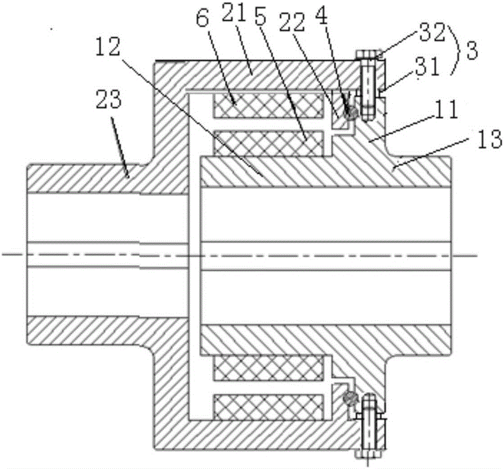
[0046] This embodiment provides a magnetic coupling, such as figure 2 shown, including:

[0047] The inner permanent magnet rotor includes an inner permanent magnet 5 and an inner cylinder part 12 for carrying the inner permanent magnet 5, and an annular flange 11 is provided on the outer wall of one end surface of the inner cylinder part 12;

[0048] The outer permanent magnet rotor includes an outer permanent magnet 6 and an outer cylinder part 21 for carrying the outer permanent magnet 6, the outer cylinder part 21 sleeves the inner cylinder part 12 away from the annular flange 11 On one side, the magnetic poles of the inner permanent magnet 5 and the outer permanent magnet 6 are matched with each other and an air gap is reserved;

[0049] The positioning couplings 3 are set to be several uniformly arranged around the axis of the coupling, and are connected and arranged between the end of the outer cylinder 21 close to the annular flange 11 and the top end of the annular ...

Embodiment 3

[0065] This embodiment provides a method for installing the magnetic coupling provided in the present invention, including the following steps: coupling the drive shaft with the outer (or inner) permanent magnet rotor of the magnetic coupling, and connecting the load shaft with the The inner (or outer) permanent magnet rotor of the magnetic coupling is connected, and then the positioning coupling of the magnetic coupling is removed.


PUM


Abstract

The invention provides a magnetic coupling and a mounting method thereof. The magnetic coupling comprises an inner permanent magnet rotor, an outer permanent magnet rotor and a plurality of positioning connectors, wherein the inner permanent magnet rotor comprises an inner permanent magnet and an inner cylinder part for bearing the inner permanent magnet, and the outer wall of the inner cylinder part is provided with an annular flange convex radially; the outer permanent magnet rotor comprises an outer permanent magnet and an outer cylinder part for bearing the outer permanent magnet, one side surface of the outer cylinder part is provided with an annular flange convex radially, and the outer cylinder part sleeves the inner cylinder part to enable magnetic poles of the inner permanent magnet and the outer permanent magnet to be mutually matched and enable an air gap to be left; and the plurality of positioning connectors are uniformly and circumferentially arranged around the axis of the coupling, and are detachably connected between the end surface of the outer cylinder part and the annular flange of the inner cylinder part to enable the two to be connected and positioned. The inner permanent magnet rotor and the outer permanent magnet rotor are not adsorbed together, the coaxiality of the two permanent magnet rotors are ensured, stability and reliability during a high-speed rotation process can be ensured, and thus, the structure is compact, the mounting is convenient, the weight is light, and the operation is stable and reliable.

Description

technical field [0001] The invention relates to the technical field of shaft couplings, in particular to a magnetic coupling and an installation method thereof. Background technique [0002] Magnetic coupling is a coupling that transmits torque by magnetic parts, which is very suitable for the transmission of torque between internal and external parts of toxic, harmful and high-pressure vessels. Magnetic couplings generally have two forms: disc-shaped and cylindrical-shaped. Since the disk-shaped coupling is composed of two facing ring magnets and the spacer, and there is an axial force between the two ring magnets, especially when the transmission power is large, the axial force is very large, and it is very difficult to overcome it. Tricky, generally less used. [0003] Cylindrical couplings usually include an inner permanent magnet rotor and an outer permanent magnet rotor sleeved outside the inner permanent magnet rotor. Magnetic steel (ie permanent magnets) are instal...

Claims


Application Information

Patent Timeline
Patent Type & Authority Applications(China)
IPC IPC(8): H02K49/10H02K15/00
CPCH02K15/00H02K49/106
Inventor 牟红刚徐俊峰
Owner JIANGSU MAGNET VALLEY TECH
Why Eureka
Try Eureka