A linkage camera control system and control method
A control system and camera technology, applied in the direction of using feedback control, TV system components, TV, etc., can solve problems such as lost steps, and achieve the effect of improving the driving torque and completely reliable rotation control
- Summary
- Abstract
- Description
- Claims
- Application Information
AI Technical Summary
Problems solved by technology
Method used
Image

Examples
Embodiment 1
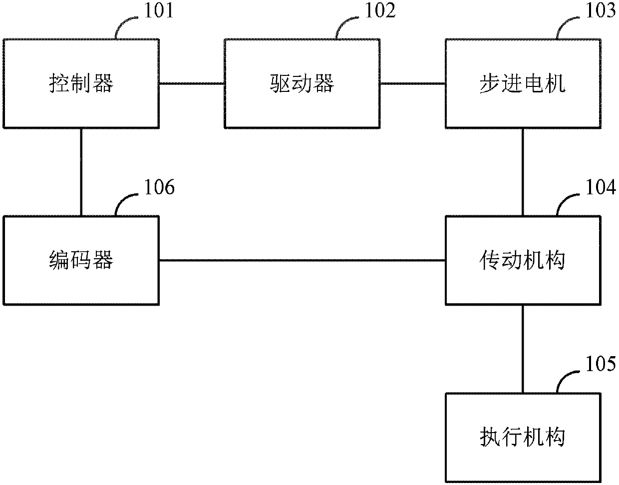
[0045] figure 1 A schematic structural diagram of a linked camera control system in Embodiment 1 of the present application is shown. As shown in the figure, the linked camera control system may include: a controller 101, a driver 102, a stepping motor 103, a transmission mechanism 104, and an actuator 105 and encoder 106, where,
[0046] The controller is configured to send pulse width modulation (PWM, PulseWidth Modulation) pulses to the driver at a pulse frequency f(n), where n represents the nth step of subdivision of the stepping motor;
[0047] The driver is used to control the rotation of the stepper motor after receiving the PWM pulse;
[0048] The transmission mechanism is used to increase the driving torque to a preset value;
[0049] The actuator is used to rotate under the driving force of the stepping motor;
[0050] The encoder is used to record the rotation angle value of the actuator;
[0051] The step is further used to drive the stepping motor at a preset...
Embodiment 2
[0102] Based on the same inventive concept, an embodiment of the present application also proposes a method for controlling a linked camera, which will be described below.
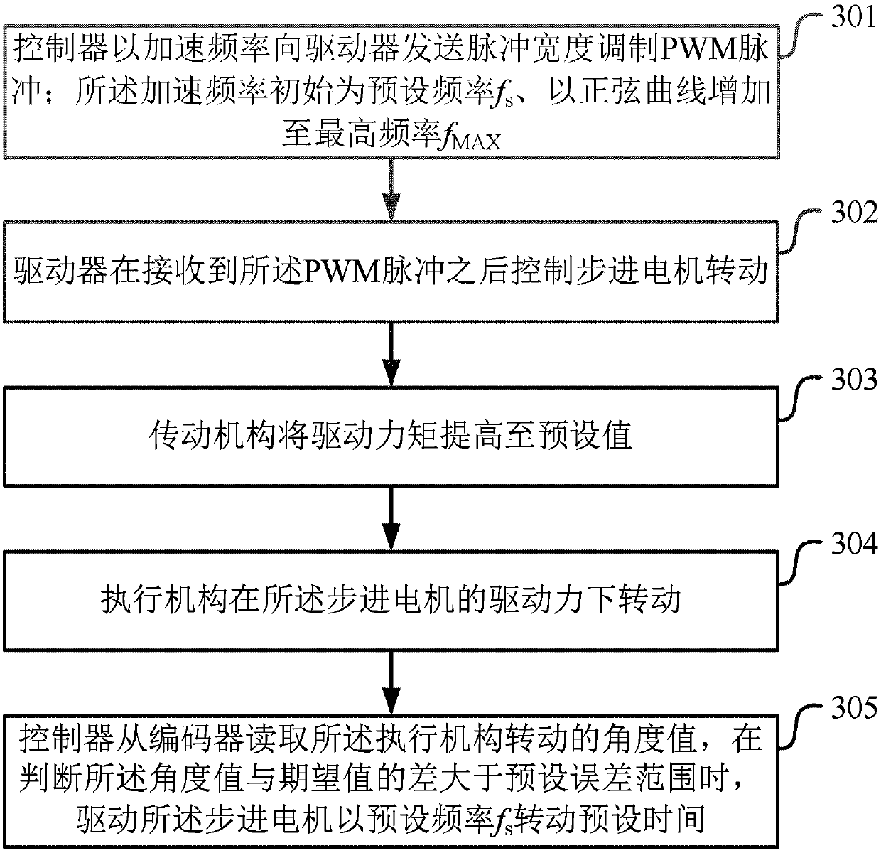
[0103] image 3 It shows a schematic flowchart of the implementation of the linked camera control method in Embodiment 2 of the present application. As shown in the figure, the linked camera control method may include the following steps:
[0104]Step 301, the controller sends pulse width modulated PWM pulses to the driver at the acceleration frequency; the acceleration frequency is initially the preset frequency f s , increasing sinusoidally to the highest frequency f MAX ;
[0105] Step 302, the driver controls the rotation of the stepper motor after receiving the PWM pulse;
[0106] Step 303, the transmission mechanism increases the driving torque to a preset value;
[0107] Step 304, the actuator rotates under the driving force of the stepping motor;
[0108] Step 305, the controller reads the rot...
Embodiment 3
[0141] The present application can be used in a specific scene where a linked camera is used for video surveillance, and the linked camera can include a wide-angle camera, a telephoto camera and the control system provided by the present application, which will be described below.
[0142] Figure 4 It shows a schematic structural diagram of the linked camera control system in the video surveillance scene in Embodiment 3 of the present application. As shown in the figure, the linked camera control system (hereinafter referred to as the control system) may include: ARM Cortex-M processor, driver, Stepper motors, reducers, rotary mirrors and absolute encoders.
[0143] The wide-angle camera and the telephoto camera are respectively connected to the control system provided by the application, and the lens of the telephoto camera is placed opposite to the rotating mirror in the control system. During specific implementation, the lens of the telephoto camera The midpoint may be on...
PUM
 Abstract
Description
Claims
Application Information
 - R&D
- Intellectual Property
- Life Sciences
- Materials
- Tech Scout
- Unparalleled Data Quality
- Higher Quality Content
- 60% Fewer Hallucinations
Browse by: Latest US Patents, China's latest patents, Technical Efficacy Thesaurus, Application Domain, Technology Topic, Popular Technical Reports.
© 2025 PatSnap. All rights reserved.Legal|Privacy policy|Modern Slavery Act Transparency Statement|Sitemap|About US| Contact US: help@patsnap.com