microphone amplifier circuit

A microphone amplifier and circuit technology, applied in transducer circuits, sensors, electrical components, etc., can solve problems such as large current consumption, low PSRR, and large output impedance of current source, and achieve power supply noise reduction, improved acoustic performance, PSRR improved effect

Active Publication Date: 2019-05-07
AAC ACOUSTIC TECH (SHENZHEN) CO LTD
View PDF4 Cites 0 Cited by
  • Summary
  • Abstract
  • Description
  • Claims
  • Application Information

AI Technical Summary

Problems solved by technology

[0004] However, in the microphone amplifier circuit of the related art, since the output impedance of the current source is not infinite, the problems of large current consumption and low PSRR generally exist in the microphone amplifier circuit, which generally can only reach 80dB, and the sensor output Electrical signals also have an impact on the performance of the microphone amplifier circuit

Method used


Image

  • microphone amplifier circuit
  • microphone amplifier circuit

Examples


Embodiment Construction

[0022] The present invention will be further described below in conjunction with the accompanying drawings and embodiments.

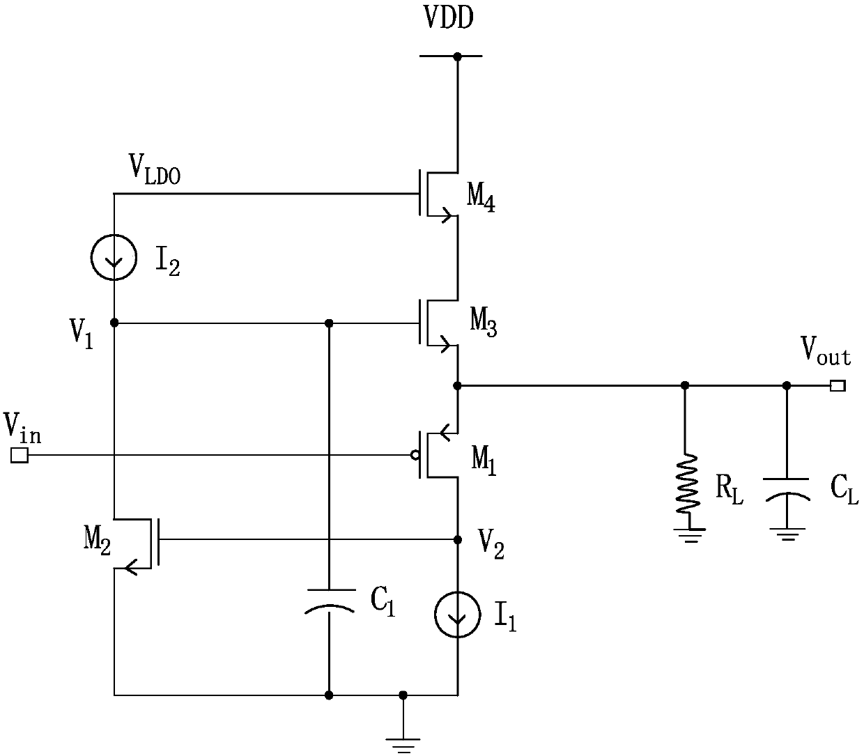
[0023] see figure 1 , is the circuit structure diagram of the microphone amplifier circuit of the first preferred embodiment of the present invention. In this embodiment, the microphone amplifier circuit 10 includes a first transistor M 1 , the second transistor M 2 , the third transistor M 3 , the fourth transistor M 4 , the first reference current source I 1 , the second reference current source I 2 and capacitor C 1 . The first transistor M 1 The gate of the microphone amplifier circuit 10 is used as the input terminal of the first transistor M 1 The source of the microphone amplifier circuit 10 is used as the output end of the first transistor M 1 The drain of the first reference current source I 1 ground, the first reference current source I 1 used to define the first transistor M 1 of quiescent current. The above circuit structure ca...


PUM


Abstract

The present invention provides a microphone amplifier circuit, comprising a first transistor, a second transistor, a third transistor, a fourth transistor, a first reference current source and a second reference current source, wherein the gate electrode of the first transistor is used as an input of the microphone amplifier circuit, the source electrode thereof is used as an output, and the drain electrode of the first transistor is grounded through the first reference current source; the gate electrode of the second transistor is connected to the drain electrode of the first transistor, the source electrode thereof is grounded, and the drain electrode thereof is connected to a reference voltage by the second reference current source; the gate electrode of the third transistor is connected to the drain electrode of the second transistor, the source electrode thereof is connected to the source electrode of the first transistor, and the drain electrode thereof is connected to the source electrode of the fourth transistor; and the gate electrode of the fourth transistor is connected to the reference voltage, and the drain electrode thereof is connected to a power supply voltage. Compared with the related art, the microphone amplifier circuit of the present invention has the advantages of low current consumption and high PSRR.

Description

【Technical field】 [0001] The invention relates to an amplifier circuit, in particular to a microphone amplifier circuit used in MEMS technology. 【Background technique】 [0002] The MEMS microphone amplifier circuit mainly includes a MEMS sensor and an ASIC (Application-Specific Integrated Circuit, Application-Specific Integrated Circuit), both of which are electrically connected to convert sound signals into electrical signals to realize the function of the microphone. [0003] In the microphone amplifier circuit of the related art, the power supply rejection ratio (Power Supply Rejection Ratio, PSRR) of the power supply at 217 Hz determines the coupling capability of noise from the power supply to the output. [0004] However, in the microphone amplifier circuit of the related art, since the output impedance of the current source is not infinite, the problems of large current consumption and low PSRR generally exist in the microphone amplifier circuit, which generally can o...

Claims


Application Information

Patent Timeline
Patent Type & Authority Patents(China)
IPC IPC(8): H04R3/00
CPCH04R3/00
Inventor 韩冬蔡东记戴有祥
Owner AAC ACOUSTIC TECH (SHENZHEN) CO LTD
Why Eureka
Try Eureka