electronic unit

An electronic unit and electrical connection technology, applied in the direction of electrical components, printed circuits, electric components, etc., can solve problems such as difficult installation of grooves, degradation of substrate strength, and substrate cracking

Active Publication Date: 2019-07-09
DENSO CORP
View PDF5 Cites 0 Cited by
  • Summary
  • Abstract
  • Description
  • Claims
  • Application Information

AI Technical Summary

Problems solved by technology

Therefore, when the size of the electronic unit is reduced, it is worryingly difficult to provide the groove in the substrate
Furthermore, for the electronic unit of JP2007-263636A, the groove provided around the temperature sensor deteriorates the strength of the substrate
Therefore, if the electronic unit is used in an environment where vibrations are transmitted, etc., the substrate may be cracked from the groove

Method used


Image

  • electronic unit
  • electronic unit
  • electronic unit

Examples


no. 1 example

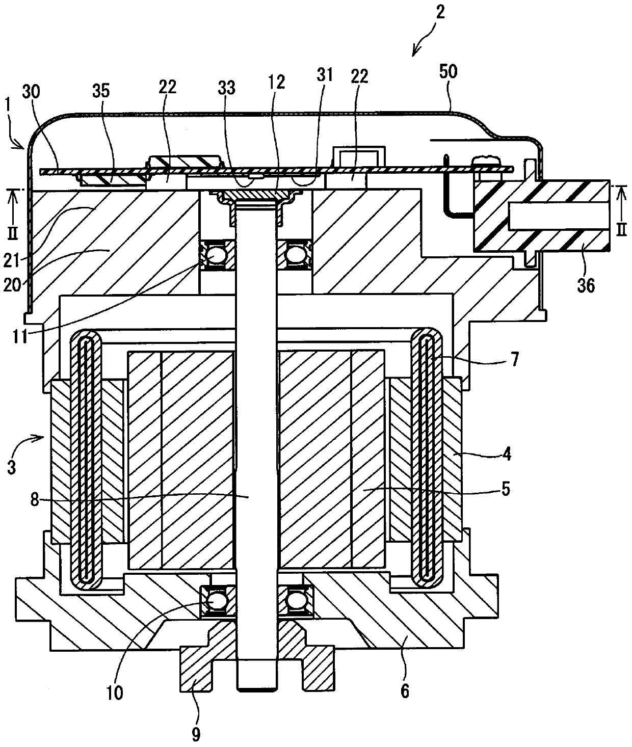
[0020] Figures 1 to 5 A first embodiment is shown in . The electronic unit 1 of the first embodiment is used in a drive device 2 that generates steering assist torque for an electric power steering system of a vehicle. Such as figure 1 As shown in , the driving device 2 includes a motor part 3 and an electronic unit 1 that controls the operation of the motor part 3 . The configuration of the motor section 3, the configuration of the electronic unit 1, and different configurations of the electronic unit 1 will be described in this order.

[0021] The configuration of the motor section 3 will be described below. The motor unit 3 includes a stator 4 and a rotor 5 . The stator 4 is formed in a cylindrical shape, and has one axial end fixed to the frame end 6 and the other axial end fixed to the heat sink 20 . The coil 7 is wound in the slots of the stator 4 . The rotor 5 has a cylindrical shape rotatably relative to the stator 4 inside the stator 4 in the radial direction. ...

no. 2 example

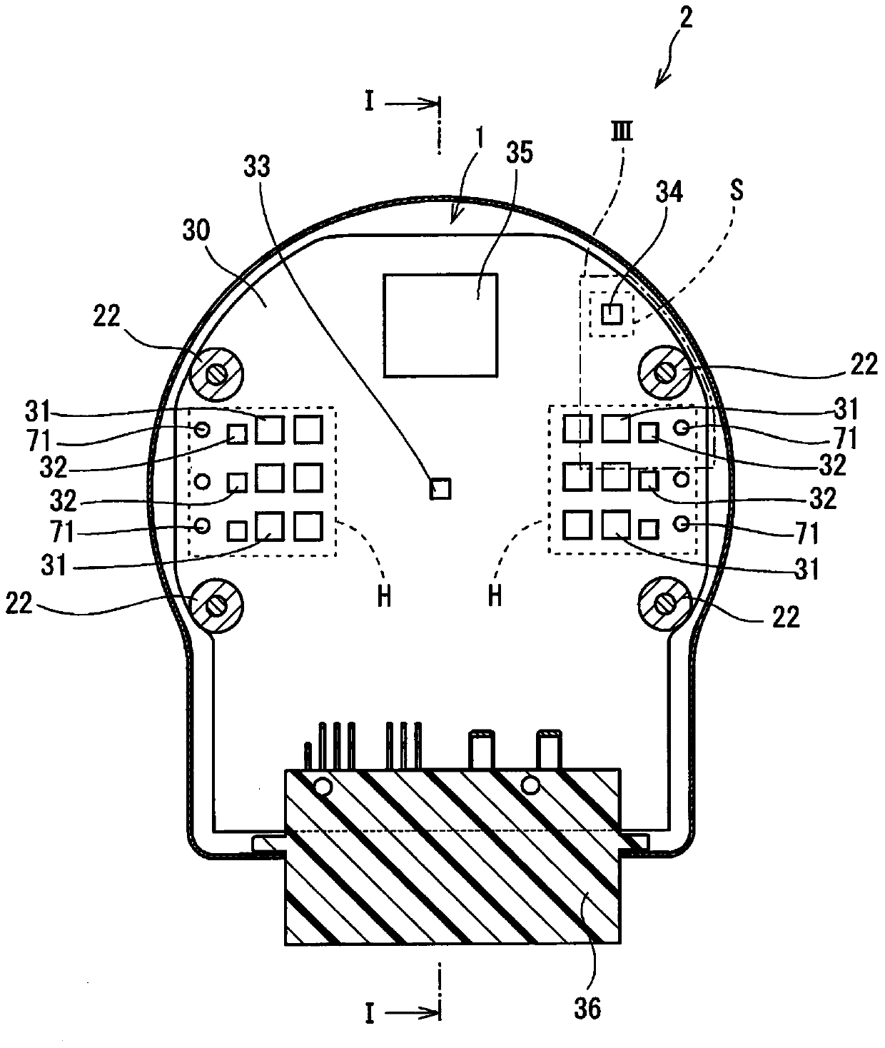
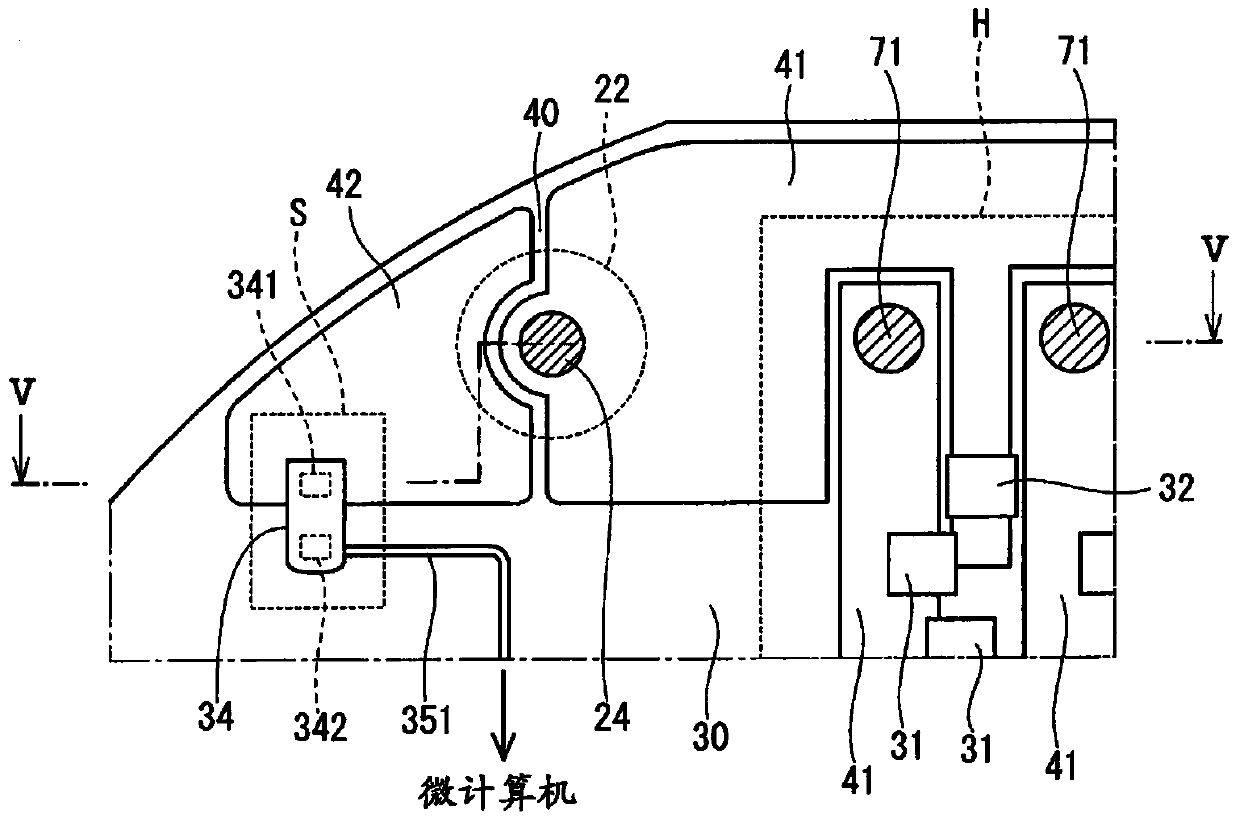
[0045] Figure 9 A second embodiment is shown in . In the second embodiment, the third interconnection 43 is provided in the surface layer of the substrate 30 . The third interconnect 43 has one end connected to the second interconnect 42 and the other end connected to the first interconnect 41 . The third interconnect 43 is provided meandering through the surface layer of the substrate 30 . When the third interconnect 43 is provided in the surface layer of the substrate 30 , the third interconnect 43 may be arranged separately from the region where the pillar 22 of the heat sink 20 is in contact with the surface layer of the substrate 30 . Furthermore, the third interconnection 43 may be arranged separately from the region where the head of the screw 24 is in contact with the surface layer of the substrate 30 . This limits the breaking of the third interconnection 43 due to the axial force of the screw 24 .

[0046] In the second embodiment, even if the screws 24 securing...


PUM


Abstract

An electronic unit includes a heat sink, a substrate, a heating component, a temperature sensor, a first interconnection, and a second interconnection. The heat sink includes a strut. The substrate is fixed to the strut of the heat sink. The heating component is mounted on the substrate to generate heat upon energization of the heating component. The temperature sensor is mounted on the substrate to detect temperature. The first interconnection is provided in a high-temperature region in which the heating component is mounted on the substrate, and is connected to the strut of the heat sink. The second interconnection is provided in a detection region in which the temperature sensor is mounted on the substrate, and is provided separately from the first interconnection. The second interconnection is connected to the strut of the heat sink and the temperature sensor.

Description

technical field [0001] The present disclosure relates to an electronic unit. Background technique [0002] There is known an electronic unit in which various electronic components including a heat generating component generating heat due to current supply, a temperature sensor detecting temperature, and a microcomputer are mounted on a substrate. The microcomputer controls current supply based on the temperature detected by the temperature sensor and the integral value of the current supplied to the heat generating component so that the temperature of the heat generating component is within an allowable temperature range. In the electronic unit of JP2007-263636A, a groove is provided in a substrate portion around a temperature sensor mounted on the substrate to suppress heat transfer of heat generated by a heat generating component to the temperature sensor. [0003] However, the substrate of the electronic unit of JP2007-263636A has a groove while still having a portion fo...

Claims


Application Information

Patent Timeline
Patent Type & Authority Patents(China)
IPC IPC(8): H05K7/20
CPCH05K7/20381B62D5/0406B62D5/0496H02K11/25H02K11/33H05K1/0201H05K1/0204H05K1/0207H05K3/0061H05K2201/062H05K2201/10151H05K2201/10166H05K2201/10409
Inventor 山本敏久
Owner DENSO CORP
Why Eureka
Try Eureka