Eureka AIR delivers breakthrough ideas for toughest innovation challenges, trusted by R&D personnel around the world.

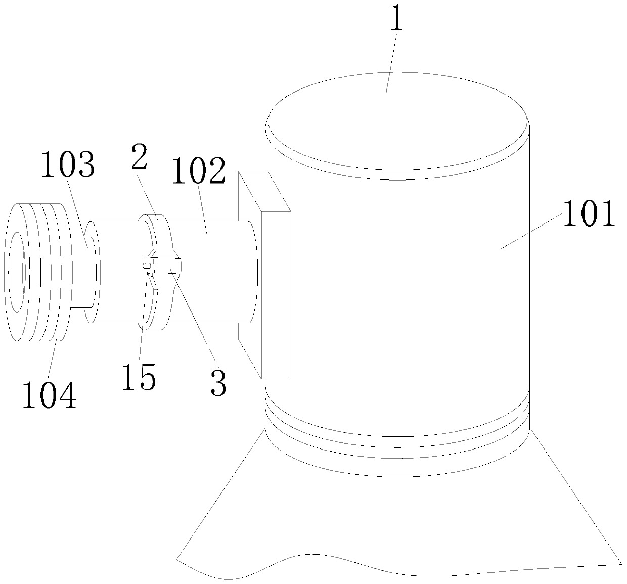
Flexible infrared temperature measuring device suitable for moving contact arm of high-voltage switch cabinet

A high-voltage switchgear and infrared temperature measurement technology, which is applied in the field of temperature measurement devices and flexible infrared temperature measurement devices, can solve problems such as poor anti-interference ability, failure to install temperature measurement probes smoothly, and unusable temperature measurement methods.

Pending Publication Date: 2020-08-28
HANGZHOU CTRLYARE ELECTRONICS
View PDF0 Cites 1 Cited by
  • Summary
  • Abstract
  • Description
  • Claims
  • Application Information

AI Technical Summary

Problems solved by technology

[0003] However, it is difficult to detect the operating temperature of the contacts in the high-voltage switchgear. This is mainly because there is high voltage in the cabinet, and the space is narrow and mostly closed. The usual temperature measurement method cannot be used; at present, the device for temperature measurement of the contacts of the high-voltage switchgear There are two types, one uses an analog temperature sensor, the temperature accuracy is not accurate, and the anti-interference ability is poor; the other is a digital temperature sensor, but it uses wired data transmission, which is limited when used in a high-voltage cabinet; the existing temperature measurement The size of the device is too large to be installed on the moving contact, and it is generally fixed on the static contact box with a smaller volume limit for the temperature measuring device; The power failure of the line has a large impact on normal production, especially for individual busy lines, because the power failure cannot even lead to the smooth implementation of the installation of the temperature measuring probe

Method used


Image

  • Flexible infrared temperature measuring device suitable for moving contact arm of high-voltage switch cabinet
  • Flexible infrared temperature measuring device suitable for moving contact arm of high-voltage switch cabinet
  • Flexible infrared temperature measuring device suitable for moving contact arm of high-voltage switch cabinet

Examples


Embodiment Construction

[0047] In order to make the purpose, features and advantages of the present application more obvious and understandable, the technical solutions in the embodiments of the present application will be clearly and completely described below in conjunction with the drawings in the embodiments of the present application. Obviously, the following The described embodiments are only some of the embodiments of the present application, but not all of them. Based on the embodiments in this application, all other embodiments obtained by persons of ordinary skill in the art without making creative efforts belong to the scope of protection of this application.

[0048] The technical solution of the present application will be further described below in conjunction with the accompanying drawings and through specific implementation methods.

[0049] In the description of the present application, it should be understood that the orientation or positional relationship indicated by the terms "up...


PUM


Abstract

The invention discloses a flexible infrared temperature measuring device suitable for a moving contact arm of a high-voltage switch cabinet. The device comprises a moving contact, a base, a contact arm, a connecting end, a plum blossom claw, a locking mechanism, a positioning hole, a lug, a buckle ring, an induction power taking coil, a female buckle, a male buckle, a belt body, a label mechanism,a shell, a circuit board assembly, an energy collection circuit, a microprocessor, a radio frequency transmitting circuit, a sensor circuit, a memory, a passive electromagnetic induction power takingcircuit, a vibration induction power taking circuit, a battery, a power switching circuit, a power protection circuit, a power state detection circuit and an infrared temperature sensor. The flexibleinfrared temperature measuring device suitable for the moving contact arm of the high-voltage switch cabinet has the advantages of being reasonable and reliable in structure and capable of effectively conducting arrangement and detection.

Description

technical field [0001] The application relates to a temperature measuring device, in particular to a flexible infrared temperature measuring device suitable for a movable contact arm of a high-voltage switch cabinet, and belongs to the technical field of infrared temperature measuring applications. Background technique [0002] High-voltage switchgear is an important electrical equipment in power plants and substations. At present, high-voltage switchgear generally adopts plug-type connection. During long-term operation, it is easy to generate heat due to long-term overloading of contacts or bus bar connections, loose joints, and aging of contacts, resulting in increased contact resistance and heating of contacts or bus bars. The temperature of the row connection will rise, which will lead to a further increase in its contact resistance, forming a vicious circle, and eventually causing the switchgear to fail. In recent years, there have been many serious accidents such as f...

Claims


Application Information

Patent Timeline
Patent Type & Authority Applications(China)
IPC IPC(8): G01J5/00G01J5/02
CPCG01J5/00G01J5/02G01J5/0205
Inventor 杨石林
Owner HANGZHOU CTRLYARE ELECTRONICS
Why Eureka
Eureka Blog
Learn More