Bridgehead settlement compensation amount test device and method

A test device and compensation technology, applied in the direction of material inspection products, etc., can solve the problems of material performance change, road surface structure affected by force, etc., achieve the effect of compact structure, ensuring accuracy, and saving research funds

Active Publication Date: 2016-11-02
SHANDONG JIAOTONG UNIV
View PDF10 Cites 4 Cited by
  • Summary
  • Abstract
  • Description
  • Claims
  • Application Information

AI Technical Summary

Problems solved by technology

[0004] Although this method can fundamentally eliminate bridgehead settlement, the material properties will change after the compensation layer expands, which will also have a certain impact on the stress of the pavement structure.

Method used


Image

  • Bridgehead settlement compensation amount test device and method
  • Bridgehead settlement compensation amount test device and method
  • Bridgehead settlement compensation amount test device and method

Examples


Embodiment 1

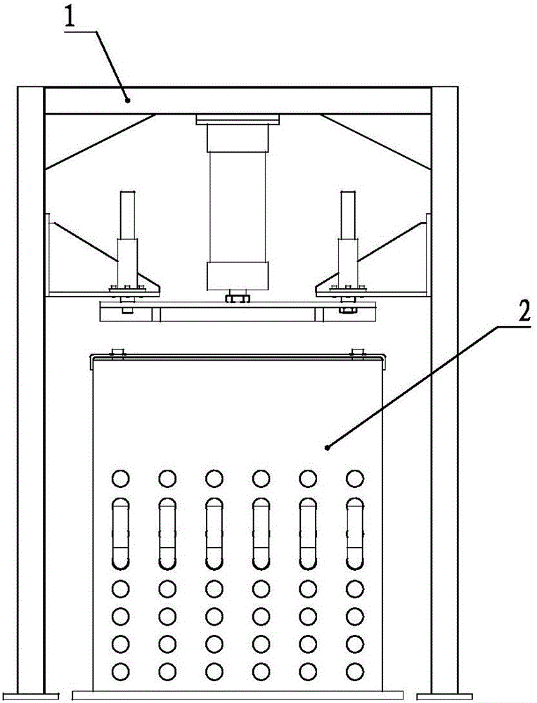
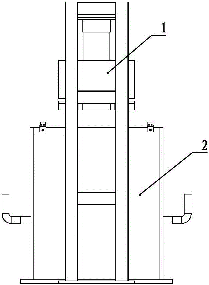
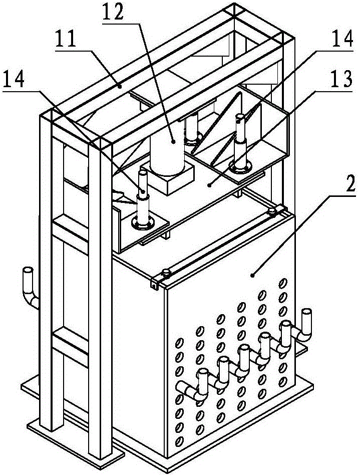
[0073] like Figure 1 to Figure 3 As shown, the bridgehead settlement compensation test device includes a pressurization unit 1, a model box 2 and a control system, and the pressurization unit 1 and the model box 2 adopt a split structure, and the model box 2 It is arranged inside the pressurizing unit 1 .

[0074] like Figure 4 As shown, the pressurizing unit 1 includes a frame 11 , an oil cylinder 12 , a pressure head 13 and a guide mechanism 14 . The frame 11 is in the shape of a "door" and includes a first leg 111 , a second leg 112 and a beam 113 arranged on the top of the first leg 111 and the second leg 112 . In order to increase the stiffness of the whole frame 11, as Figure 7 As shown, the first leg 111 and the second leg 112 are square frames welded by several square steel pipes, and the crossbeams 113 are two, which are respectively arranged on the first leg 111 Ribs 114 are provided between the first leg 111 and the beam 13 and between the second leg 112 and ...

Embodiment 2

[0083] like Figure 16 As shown, the pressurization unit includes an indenter placed on the second press plate, on which a heavy object of a certain weight is placed, and the subgrade pavement model is pressurized by the gravity of the heavy object itself. All the other structures are the same as in Embodiment 1.

[0084] A method for testing bridgehead settlement compensation, comprising the following steps:

[0085] a), set the subgrade pavement model, the subgrade pavement model is successively subgrade, subbase, base and surface layer from bottom to top, and a compensation layer is arranged in the subgrade wherein, the specific parameters are:

[0086] The pre-embedded depth of the compensation layer is 70cm, and the thickness is 11cm;

[0087] The mixing ratio of gypsum and fly ash in the compensation layer is 1:2;

[0088] The materials of the road base, subbase, base and surface course are well-graded gravel mixture, fly ash-alkali slag stabilized soil, cement stabil...


PUM

PropertyMeasurementUnit
thicknessaaaaaaaaaa
thicknessaaaaaaaaaa
thicknessaaaaaaaaaa

Abstract

The invention discloses a bridgehead settlement compensation amount test device and method. The device comprises a pressurization unit, a model case and a control system. The pressurization unit comprises a frame, an oil cylinder, a pressure head and a guiding mechanism. The frame has a U-shaped structure and comprises a first support leg, a second support leg and a crossbeam. The oil cylinder is arranged in the middle of the crossbeam, the cylinder body of the oil cylinder is fixedly connected to the crossbeam, the end of a piston rod is provided with the pressure head and the guiding mechanism is arranged between the pressure head and the frame. The model case comprises a case body, a roadbed pavement model, a displacement sensor and several steel pipes. The roadbed pavement model is arranged in the case body. The upper part of the case body is provided with the displacement sensor. The several steel pipes go through the case body and are connected to the case body. The steel pipes are provided with water leakage apertures. Through simulation of different pavement structures, a relationship of a swelling amount increasing rule, compensation layer position, thickness, lateral confinement and compaction rate, and a lime slurry injection amount is researched and the relationship lays the foundation of design index formation.

Description

technical field [0001] The invention relates to the technical field of bridge construction, in particular to a bridge head settlement compensation test device and a test method. Background technique [0002] Vehicle jumping at the bridge head not only affects the comfort of driving on the road, but more importantly, it is prone to traffic safety accidents. Under the existing technology, there are many methods to deal with bridge head jumping, and many measures have been proposed in terms of foundation treatment, subgrade filling selection, construction process control, and post-maintenance. However, these methods either have poor treatment effects or high treatment costs. Not very ideal. In addition, from the perspective of settlement mechanism, the occurrence of settlement differences is inevitable, and no matter what measures are taken, they can only solve the problem of the size of the settlement. [0003] According to previous studies, titanium gypsum and fly ash will ...

Claims


Application Information

Patent Timeline
Patent Type & Authority Applications(China)
IPC IPC(8): G01N33/42
CPCG01N33/42
Inventor 赵之仲刘桂强黎奎王琨
Owner SHANDONG JIAOTONG UNIV
Why Eureka
Try Eureka