
Sound pressure and vibration velocity cross spectrum method-based vector array port and starboard discrimination method
A technology of vector array and cross-spectral method, which is applied in the field of starboard and starboard resolution of vector array, and can solve the problems of uneven resolution of port and starboard and low resolution accuracy of port and starboard of vector array.
- Summary
- Abstract
- Description
- Claims
- Application Information
AI Technical Summary
Problems solved by technology
Method used
Image

Examples
specific Embodiment approach 1
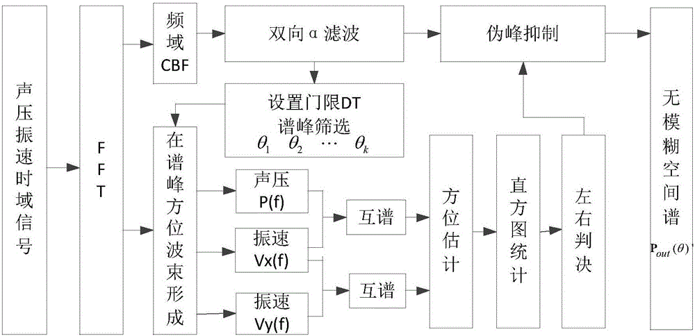
[0087] A kind of vector array starboard and starboard discrimination method based on sound pressure and vibration velocity cross-spectrum method in this embodiment, combined with figure 2 and image 3 As shown, the method is realized through the following steps:
[0088] Step 1. After the sound pressure signal received by the multi-element array is converted into a frequency domain signal, the frequency domain broadband conventional beamforming process is performed to obtain the original spatial spectrum matrix P out (θ); wherein, the spatial spectrum matrix refers to the matrix of the output spatial spectrum type;
[0089] Step 2. For the original spatial spectrum matrix P obtained in step 1 out (θ) performs bidirectional first-order recursive filtering to obtain the smoothed spatial spectrum P α (θ);
[0090] Step 3. According to the smooth spatial spectrum P obtained in step 2 α (θ), in the smooth space spectrum P α (θ) on the basis of improving D T decibels to obta...
specific Embodiment approach 2
[0097] The difference from Embodiment 1 is that in this embodiment, based on the sound pressure and vibration velocity cross-spectrum method of the vector array left and right sides, the frequency-domain broadband conventional beamforming is performed on the sound pressure signal received by the multi-element array as described in step 1. (CBF) processing to obtain the original spatial spectrum matrix P out The process of (θ) is,
[0098] Step 11, performing fast Fourier transform (abbreviated as FFT) to the received sound pressure and vibration velocity time domain signals into frequency domain signals;
[0099] Step 12: Perform conventional beamforming (referred to as CBF) processing on each frequency point signal in the frequency domain signal working frequency band bandwidth within the B range, obtain the spatial spectrum of each frequency point, and output; and express the spatial spectrum as P( f i ,θ), and
[0100] P(f i ,θ)=a(f i ,θ) H R(f i )a(f i ,θ); where,...
specific Embodiment approach 3
[0106] The difference from the specific embodiment 1 or 2 is that in this embodiment, a vector array based on sound pressure and vibration velocity cross-spectrum method for distinguishing left and right sides, the original spatial spectrum matrix P obtained in step 1 is described in step 2. out (θ) performs bidirectional first-order recursive filtering to obtain the smoothed spatial spectrum P α The process of (θ) is,
[0107] Step 21, using a two-way first-order recursive filter, that is, the α filter is used to filter the original spatial spectrum matrix P out (θ) for smoothing and filtering; at the same time extract the original spatial spectrum matrix P out (θ) peak;
[0108] Step 22. The original spatial spectrum matrix P out (θ) performs two-way α filtering to get P α (θ), according to the adjustability of the filter coefficient, the filter coefficient is adjusted to be smaller, so that the filtering effect is more obvious, and the obtained P α(θ) is also flatter. ...
PUM
 Abstract
Description
Claims
Application Information