
Sandblasting machine

A technology of sand blasting machine and spray gun, applied in the field of sand blasting machine, can solve the problems of uneven impact of sand blasting and the like

Active Publication Date: 2018-01-12
SHENZHEN YINXIU TECH CO LTD
View PDF6 Cites 0 Cited by
  • Summary
  • Abstract
  • Description
  • Claims
  • Application Information

AI Technical Summary

Problems solved by technology

[0007] The object of the present invention is to provide a sandblasting machine to solve the technical problem of uneven impact of sandblasting when removing the passivation layer and roughening the bonding surface in the sandblasting operation in the prior art

Method used


Image

  • Sandblasting machine
  • Sandblasting machine
  • Sandblasting machine

Examples


Embodiment 1

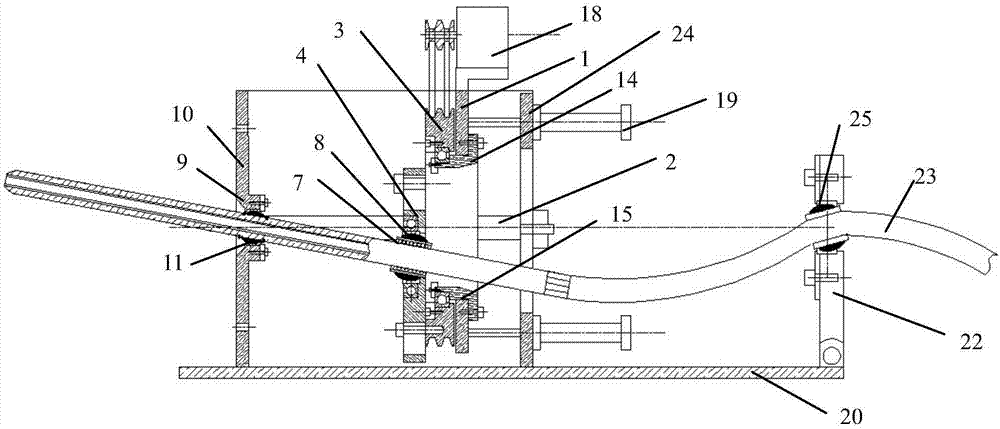
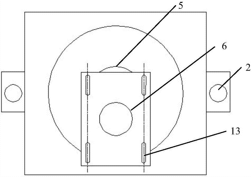
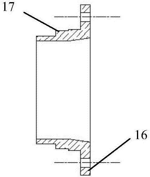
[0049] Such as figure 1 with 2 As shown, a sandblasting machine is provided in this embodiment, the sandblasting machine includes a focusing mechanism and a swing mechanism, and the swing mechanism is connected to the focus mechanism;

[0050] The focusing mechanism includes a focusing platform 1 and a sliding shaft 2, the sliding shaft 2 is placed horizontally, the focusing platform 1 and the sliding shaft 2 are vertically arranged, and the focusing platform 1 and the sliding shaft 2 are vertically arranged. sliding connection;

[0051] The oscillating mechanism includes a passive rotating wheel 3 and an eccentric block 4, the passive rotating wheel 3 is rotationally connected with the focusing platform 1, the eccentric block 4 is arranged on the passive rotating wheel 3, and is located on the passive rotating wheel 3. Wheel 3 is away from the side of the focusing platform 1;

[0052] The center of the passive rotating wheel 3 is provided with a runner center hole 5, and t...


PUM


Abstract

The invention provides a sand blasting machine, and relates to the technical field of treatment equipment of steel tube inner wall dirt and a passivation layer. The sand blasting machine comprises a focusing mechanism and a swing mechanism, and further comprises a spray gun bracket; the swing mechanism is connected with the focusing mechanism; the swing mechanism comprises a driven rotary wheel and an eccentric block; the driven rotary wheel is rotatably connected with the focusing platform, and is positioned at one side, deviating from the focusing platform, of the driven rotary wheel; a rotary wheel central hole is formed in the center of the driven rotary wheel; a spray gun hole is formed in the eccentric block; a spray gun is inserted into the spray gun hole through a joint bearing; a centre line of the rotary wheel central hole and a central line of the spray gun hole are not on the same horizontal line; the tail part of the spray gun is connected with the spray gun hole; and the spray gun bracket and the focusing platform are arranged in parallel. The sand blasting machine provided by the invention solves the technical problem of uneven sand blasting collision in a current sand blasting process.

Description

technical field [0001] The invention relates to the technical field of equipment for treating dirt and passivation layers on the inner wall of steel pipes, in particular to a sandblasting machine. Background technique [0002] Steel-plastic composite pipe is a kind of steel-plastic composite pipe made on the basis of traditional galvanized steel pipe, sprayed plastic on its inner wall or lined with plastic PE pipe. It has excellent performance, especially good corrosion resistance, and is widely used in various fields. been widely used in. The most widely used steel-plastic composite pipe at present is a pipe made of galvanized steel pipe material on the outside, and the inner wall of the galvanized steel pipe is bonded with polyethylene plastic pipe or sprayed with polyethylene plastic powder. [0003] In order to achieve a better bonding effect between the plastic and the steel pipe, the steel pipe needs to be sand blasted. Specifically, the sandblasting process is to re...

Claims


Application Information

Patent Timeline
Patent Type & Authority Patents(China)
IPC IPC(8): B24C1/04B24C3/32B24C9/00
CPCB24C1/04B24C3/325B24C9/00
Inventor 王智勇王梦晓
Owner SHENZHEN YINXIU TECH CO LTD
Learn More