
Chemical fabric ventilation device

A technology of ventilation device and chemical fiber cloth, which is applied in the direction of heating device, drying gas arrangement, dryer, etc., can solve the problems of slow processing speed, low degree of automation, and low production capacity of the whole line, so as to improve the speed of ventilation and save manpower The effect of high material resources and high degree of automation

Inactive Publication Date: 2016-11-09
长兴县鑫盛轻纺有限公司
View PDF7 Cites 0 Cited by
  • Summary
  • Abstract
  • Description
  • Claims
  • Application Information

AI Technical Summary

Problems solved by technology

[0002] Chemical fiber fabric is a new type of clothing material developed in modern times. There are many types. Here it mainly refers to pure spinning, blended or interwoven fabric processed from chemical fiber. Chemical fiber fabric needs to be ventilated during use to make the clothes more comfortable. Comfortable, and the breathable treatment of chemical fiber fabrics at this stage mostly starts from weaving, using thread materials with good air permeability. This processing method is difficult to process chemical fiber fabrics woven from thread materials with poor air permeability. The processing speed of the device to the product is too slow, and it cannot directly perform ventilation treatment on the chemical fiber cloth, resulting in low production capacity of the whole line, affecting the ventilation quality of the chemical fiber cloth, and the degree of automation is low, requiring a lot of manpower and material resources as support, increasing the ventilation the cost of

Method used


Image

  • Chemical fabric ventilation device
  • Chemical fabric ventilation device
  • Chemical fabric ventilation device

Examples


Embodiment Construction

[0014] The following will clearly and completely describe the technical solutions in the embodiments of the present invention with reference to the accompanying drawings in the embodiments of the present invention. Obviously, the described embodiments are only some, not all, embodiments of the present invention. Based on the embodiments of the present invention, all other embodiments obtained by persons of ordinary skill in the art without making creative efforts belong to the protection scope of the present invention.

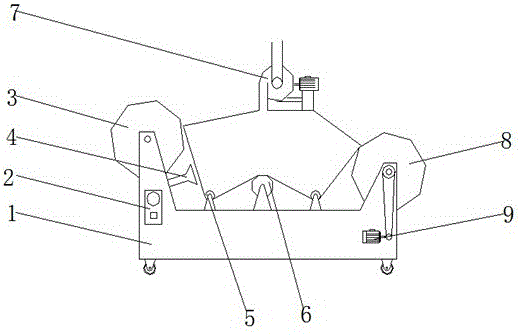
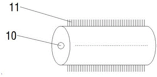
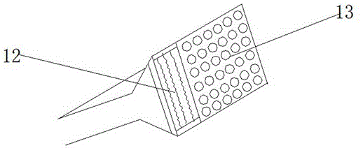
[0015] see Figure 1-3 , the present invention provides a technical solution: a chemical fiber cloth ventilation device, including a base 1, a control panel 2, a cloth storage drum 3, a drying and heating nozzle 4, a fixed roller 5, a ventilation roller 6, a dust suction fan 7, and a cloth Storage roller 8, drive motor 9, support shaft 10, ventilation needle 11, heating wire 12 and tuyere 13, control panel 2 is provided on the upper side of the base 1, and cas...


PUM


Abstract

The invention discloses a chemical fabric ventilation device. The chemical fabric ventilation device comprises a base, a control panel, a cloth storage roller, a drying heating sprayer, fixed rolling shafts, a ventilation roll shaft, a dust suction ventilator, a cloth accommodation roller, a driving motor, a support shaft, ventilation needles, electric heating wires and air openings, wherein the control panel is arranged on the upper side of the base; the cloth storage roller is arranged on the upper side of the control panel; the drying heating sprayer is arranged on the right and lower side of the cloth storage roller; the fixed rolling shafts are arranged on the right side of the drying heating sprayer; the ventilation roll shaft is arranged on the right side of the fixed rolling shafts; the dust suction ventilator is arranged on the upper side of the ventilation roll shaft; the cloth accommodation roller is arranged on the right and lower side of the dust suction ventilator; the driving motor is arranged on the lower side of the cloth accommodation roller; the support shaft is arranged on the center of the ventilation roll shaft; and the ventilation needles are arranged on the outer wall of the ventilation roll shaft. According to the chemical fabric ventilation device, the ventilation roll shaft is arranged, so that the automation degree is high; a great amount of manpower and material resource is saved; and the ventilation effect is good.

Description

technical field [0001] The invention relates to the technical field of chemical fiber cloth ventilation, in particular to a chemical fiber cloth ventilation device. Background technique [0002] Chemical fiber fabric is a new type of clothing material developed in modern times. There are many types. Here it mainly refers to pure spinning, blended or interwoven fabric processed from chemical fiber. Chemical fiber fabric needs to be ventilated during use to make the clothes more comfortable. Comfortable, and the breathable treatment of chemical fiber fabrics at this stage mostly starts from weaving, using thread materials with good air permeability. This processing method is difficult to process chemical fiber fabrics woven from thread materials with poor air permeability. The processing speed of the device to the product is too slow, and it cannot directly perform ventilation treatment on the chemical fiber cloth, resulting in low production capacity of the whole line, affect...

Claims


Application Information

Patent Timeline
IPC IPC(8): B26F1/24B26D7/27F26B23/06F26B21/00
CPCB26F1/24B26D7/27F26B21/00F26B23/06
Inventor 许志强刘建新李芳彬
Owner 长兴县鑫盛轻纺有限公司
Learn More