A pu round foam high pressure foaming unit

一种高压发泡、机组的技术,应用在发泡机组领域,能够解决泡沫性能不均、混合不均、孔径不均等问题,达到物理性能好、均匀效果好、孔径均匀细腻的效果

Active Publication Date: 2017-08-08
HARBIN KAIRUIDA SPONGE MFG
View PDF5 Cites 0 Cited by
  • Summary
  • Abstract
  • Description
  • Claims
  • Application Information

AI Technical Summary

Problems solved by technology

[0004] The present invention aims to solve the problems that the existing PU round foam foaming unit adopts the low-pressure foaming method, and there is uneven mixing, resulting in uneven foam performance, uneven pore size and flow marks, and provides a PU round foam high-pressure foaming method. unit

Method used


Image

  • A pu round foam high pressure foaming unit
  • A pu round foam high pressure foaming unit
  • A pu round foam high pressure foaming unit

Examples


specific Embodiment approach 1

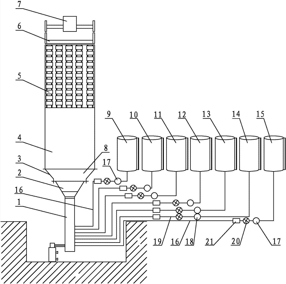
[0019] Specific implementation mode one: combine Figure 1 ~ Figure 3 Describe this embodiment, this embodiment comprises mixing head 1, conical shaft 2, circular shaft 4, chain plate drive cylinder 5, cutting mechanism 6, bubble-entrapping mechanism 7, cylindrical plastic film 8, the first raw material tank 9, The second raw material tank 10, the third raw material tank 11, the fourth raw material tank 12, the fifth raw material tank 13, the sixth raw material tank 14, the seventh raw material tank 15, two low-pressure feed pipes 16, two low-pressure pumps 17, Three connecting rods 3, five high-pressure pumps 18, five high-pressure feed pipes 19, seven flowmeters 20 and seven pressure gauges 21,

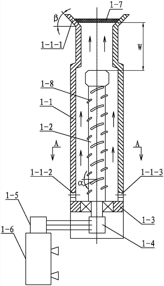
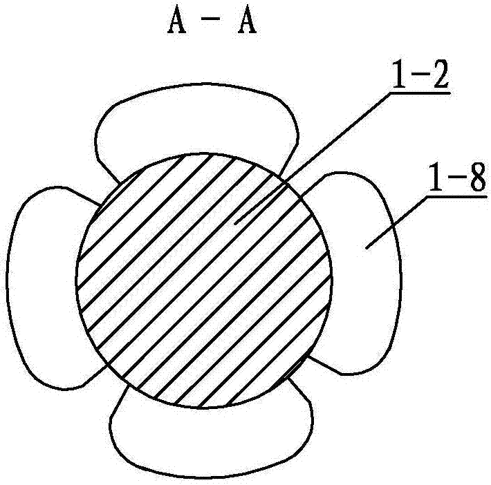
[0020] The mixing head 1 includes a housing 1-1, a stirring shaft 1-2, a base 1-3, a driven pulley 1-4, a driving pulley 1-5, a stirring motor 1-6, a balance grid 1-7 and several Blades 1-8,

[0021] The stirring shaft 1-2 is set in the housing 1-1, the lower end of the stirring s...

specific Embodiment approach 2

[0026] Specific implementation mode two: combination figure 2 The present embodiment will be described. The height of the pressure buffer zone W in the present embodiment is 150 mm to 300 mm. The pressure buffer W increases the space of the cavity, and the longer cavity makes the raw materials mix continuously while reducing the multi-directionality of the pressure and flow rate brought by the vortex speed. Other components and connections are the same as those in the first embodiment.

specific Embodiment approach 3

[0027] Specific implementation mode three: combination figure 2 The present embodiment will be described. The height of the pressure buffer zone W in the present embodiment is 250 mm. The pressure buffer W increases the space of the cavity, and the longer cavity makes the raw materials mix continuously while reducing the multi-directionality of the pressure and flow rate brought by the vortex speed. Other components and connections are the same as those in the second embodiment.


PUM

PropertyMeasurementUnit
angleaaaaaaaaaa
angleaaaaaaaaaa
angleaaaaaaaaaa

Abstract

The invention discloses a high-pressure foaming unit for PU round foams, and the high-pressure foaming unit aims at solving the problems that the pore diameter is uneven and flowing mark is generated due to the fact that an existing PU round foam foaming unit adopts a low-pressure foaming mode. Multiple blades are installed on a stirring shaft and arranged at intervals according to a double-head helical line, and the helical angle of each blade ranges from 5 degrees to 15 degrees; a pressure buffering zone is performed between a balancing mesh grille and the upper end face of the stirring shaft, a mixing head, a cone-shaped channel, connecting rods, a circular channel, chain plate transmission cylinders, a cut-off mechanism and a foam clamping mechanism are sequentially arranged from bottom to top, and cylindrical plastic film is laid along the inner walls of the cone-shaped channel, the circular channel and the chain plate transmission cylinders; a first raw material tank and a seventh raw material tank are each connected with a low-pressure feeding hole through a low-pressure feeding pipe, and a second raw material tank, a third raw material tank, a fourth raw material tank, a fifth raw material tank and a sixth raw material tank are each connected with a high-pressure feeing hole through a high-pressure feeding pipe. The high-pressure foaming unit is used for producing the PU round foams.

Description

technical field [0001] The invention relates to a foaming unit, in particular to a PU round foam high-pressure foaming unit. Background technique [0002] The PU (polyurethane) bulk foam continuous production line includes flat foam production line and round foam production line. As we all know, the flat foam production line produces products with fine and uniform pore size, stable performance, and high-quality products. Therefore, the flat foam production line is being used more and more more. However, the round bubble also has many advantages: the round bubble coil is relatively long, has no joints, the width of the coil can be changed flexibly, the equipment occupies a small area, uses less manpower, less waste of raw materials, and less investment. [0003] The existing PU (polyurethane) round foaming machine adopts the low-pressure foaming method (that is, the low-pressure gas injection method). 2 Enter the mixing head for mixing and foaming. Since the pressure of eac...

Claims


Application Information

Patent Timeline
Patent Type & Authority Patents(China)
IPC IPC(8): B29C44/34B29K75/00
CPCB29C44/34B29C44/3442B29K2075/00
Inventor 李业光唐雪飞贾冠群王爽
Owner HARBIN KAIRUIDA SPONGE MFG
Why Eureka
Try Eureka