Vehicle body of railroad vehicle and railroad vehicle

A technology for railway vehicles and car bodies, which is applied to railway car bodies, railway car body parts, transportation and packaging, etc., can solve the problems of increasing the welding workload of car body connections, welding deformation, and reducing work efficiency, and achieves a reduction in welding work. quantity, improve welding efficiency, and ensure the effect of verticality

Active Publication Date: 2016-11-09
CRRC TANGSHAN CO LTD
View PDF6 Cites 17 Cited by
  • Summary
  • Abstract
  • Description
  • Claims
  • Application Information

AI Technical Summary

Problems solved by technology

[0005] The present invention provides a railway vehicle body and a railway vehicle to overcome the problem in the prior art that when the side wall and the end wall are connected together by longitudinal beams, the welding workload of the vehicle body connection is increased, welding deformation is caused, and work efficiency is reduced The problem

Method used


Image

  • Vehicle body of railroad vehicle and railroad vehicle
  • Vehicle body of railroad vehicle and railroad vehicle
  • Vehicle body of railroad vehicle and railroad vehicle

Examples


Embodiment 1

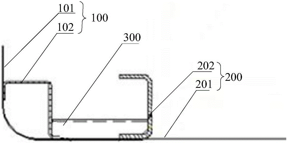
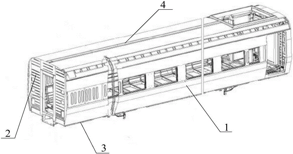
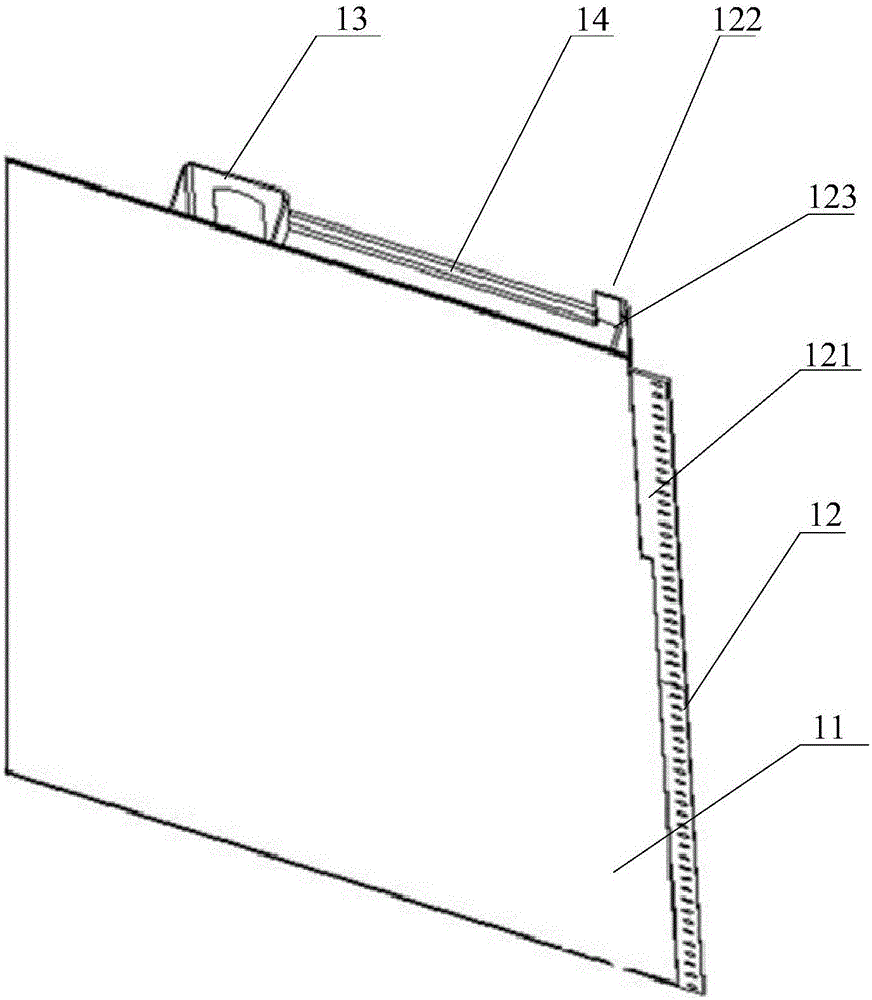
[0055] figure 2 A schematic diagram of the overall structure of the railway vehicle body provided by Embodiment 1 of the present invention; image 3 A schematic structural diagram of a side wall of a railway vehicle body provided in Embodiment 1 of the present invention; Figure 4 Schematic diagram of the structure of the end wall of the railway vehicle body provided by Embodiment 1 of the present invention; Figure 5 A schematic diagram of the connection between the side wall and the end wall of the railway vehicle body provided by Embodiment 1 of the present invention; Image 6 A top view of the connection between the side wall and the end wall of the railway vehicle body provided by Embodiment 1 of the present invention.

[0056] Please also refer to the following Figure 2 to Figure 6, the railway vehicle body provided in this embodiment includes: side wall 1, end wall 2, underframe 3, roof 4, wherein: side wall 1 and end wall 2 are welded on the underframe 3 respectiv...

Embodiment 2

[0086] This embodiment provides a railway vehicle. The railway vehicle provided in this embodiment includes a bogie and the railway vehicle body provided in Embodiment 1 of the present invention, wherein the railway vehicle body is arranged on the bogie.

[0087] Specifically, the structure and function of the railway vehicle body are similar to those of the foregoing embodiments, and will not be repeated here.


PUM


Abstract

The invention provides a vehicle body of a railroad vehicle and the railroad vehicle. The vehicle body of the railroad vehicle comprises a lateral wall, an end wall, a bottom frame and a roof, wherein the lateral wall comprises a Z-shaped end stand column; the end wall comprises a U-shaped end corner column; one part, far away from an end wall plate, on the bottom surface of the U-shaped end corner column is provided with a concave surface; an end face, welded with a lateral wall plate, of the Z-shaped end stand column is overlapped on the concave surface; the overlapping amount of overlapping the end face, welded with the lateral wall plate, of the Z-shaped end stand column on the concave surface is determined according to a deviation amount of the length of the bottom frame in the direction of the lateral wall and the length of the lateral wall; the Z-shaped end stand column is connected with the concave surface through a welding manner. According to the vehicle body of the railroad vehicle and the railroad vehicle, provided by the invention, the perpendicularity of the end wall installation can be guaranteed, the welding working amount of connecting the vehicle body can be reduced and the working efficiency of welding is improved.

Description

technical field [0001] The invention relates to railway vehicle technology, in particular to a railway vehicle body and a railway vehicle. Background technique [0002] The car body of a railway vehicle is mainly composed of several parts such as roof, side wall, end wall, and underframe, wherein the edges of each part are welded together to form a box-shaped car body structure. In the composition process of the car body, the side wall is usually welded to the bottom frame first, and then the end wall is welded to the bottom frame and the side wall, because the length of the bottom frame in the side wall direction and the length of the side wall are different There will be a certain deviation in the production process. When the side wall is welded to the bottom frame, the length of the bottom frame in the direction of the side wall is not exactly equal to the length of the side wall. In this way, after the end wall is welded to the bottom frame and When it is on the side wa...

Claims


Application Information

Patent Timeline
Patent Type & Authority Applications(China)
IPC IPC(8): B61D17/06B61D17/08
CPCB61D17/043B61D17/06B61D17/08
Inventor 张硕韶高军张锦华侯建英
Owner CRRC TANGSHAN CO LTD
Why Eureka
Try Eureka