
Fiber cutting-off mechanism

A cutting mechanism and fiber technology, which is applied in fiber cutting, fiber processing, textile and papermaking, etc., can solve the problems of unimproved processing efficiency, large pressure area, poor cutting, etc., and achieves compact structure, high reliability and high performance. fast effect

Inactive Publication Date: 2016-11-09
XINCHANG YIYUAN PRECISION MACHINERY
View PDF0 Cites 0 Cited by
  • Summary
  • Abstract
  • Description
  • Claims
  • Application Information

AI Technical Summary

Problems solved by technology

The cutting mechanism of the existing cutting machine is usually a horizontal strip-shaped parallel cutter, which cuts the material in parallel, has a large pressure area, requires a large driving force, and is easy to cause problems such as poor cutting, and the processing efficiency needs to be improved.

Method used


Image

  • Fiber cutting-off mechanism

Examples


Embodiment Construction

[0012] Below in conjunction with accompanying drawing, the present invention will be further described:

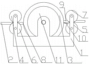
[0013] A fiber cutting mechanism, including a frame 1, a supporting plate 2, a cutter roller 3, a first pinch wheel 4, a second pinch wheel 5, a first driven wheel 6, a second driven wheel 7, and a lower cutter 8 , the upper cutter 9 and the guide plate 10, the two ends of the frame 1 are provided with a supporting plate 2, the cutter roller 3 is arranged on the frame 1, and the supporting plate 2 is provided with a lower cutter 8 near the cutter roller 3, The rear of the lower cutter 8 is provided with the first pinch wheel 4, the first driven wheel 6 is arranged below the first pinch wheel 4, and the supporting plate 2 on the side different from the supporting plate 2 of the lower cutter 8 is provided with an upper cutting wheel. Knife 9, a second pinch wheel 5 is arranged behind the upper cutter 9, a second driven wheel 7 is arranged above the second pinch wheel 5, and ...


PUM


Abstract

The invention relates to a fiber cutting-off mechanism. The fiber cutting-off mechanism is characterized by comprising a rack, supporting plates, a cutter roller, a first pressing wheel, a second pressing wheel, a first driven wheel, a second driven wheel, a lower cutter, an upper cutter and a guide plate, wherein the supporting plates are arranged at the two ends of the rack; the cutter roller is arranged on the rack; the lower cutter is arranged at the part, close to the cutter roller, of one supporting plate; the first pressing wheel is arranged behind the lower cutter; the first driven wheel is arranged below the first pressing wheel; the upper cutter is arranged on the supporting plate on one side opposite to the supporting plate for arranging the lower cutter; the second pressing wheel is arranged behind the upper cutter; the second driven wheel is arranged above the second pressing wheel; and the guide plate is arranged below the upper cutter. According to the fiber cutting-off mechanism, cutting mechanisms are arranged on the two sides so that the working efficiency of the cutting-off mechanism is improved; and a herringbone cutter is utilized so that materials are prevented from being dispersed toward four sides and shaft clamping is prevented.

Description

technical field [0001] The invention relates to a fiber cutting mechanism. Background technique [0002] The fiber cutting machine is a general-purpose cutting equipment with a very wide range of applications. It can cut a variety of different types of raw materials according to different requirements to meet people's needs for materials. Divided into rotary hob fiber cutter, guillotine cutter, parallel blade cutter, etc. The cutting mechanism of the existing cutting machine is usually a horizontal strip-shaped parallel cutter, which cuts the material in parallel, has a large pressure area, requires a large driving force, and is easy to cause problems such as poor cutting, and the processing efficiency needs to be improved. Contents of the invention [0003] In view of the problems existing in the prior art, the object of the present invention is to provide a technical solution of a fiber cutting mechanism. [0004] The fiber cutting mechanism is characterized in that it...

Claims


Application Information

Patent Timeline
Patent Type & Authority Applications(China)
IPC IPC(8): D01G1/00
CPCD01G1/00
Inventor 王占元刘元栋
Owner XINCHANG YIYUAN PRECISION MACHINERY
Learn More