Reeding frame

A technology of movable rods and fixed seats, which is applied in the field of reed racks, can solve the problems of large space, affecting the passability and cleanliness of the site, and achieve the effect of convenient use, simple structure and clean site

Inactive Publication Date: 2016-11-09
安徽江南明泽纺织有限公司
View PDF0 Cites 0 Cited by
  • Summary
  • Abstract
  • Description
  • Claims
  • Application Information

AI Technical Summary

Problems solved by technology

In the traditional reed operation, the reed is placed on the reed bench. The traditional reed bench not only takes up a lot of space, but also affects the passability and cleanliness of the site when the reed operation is not in progress.

Method used


Image

  • Reeding frame
  • Reeding frame

Examples


Embodiment 1

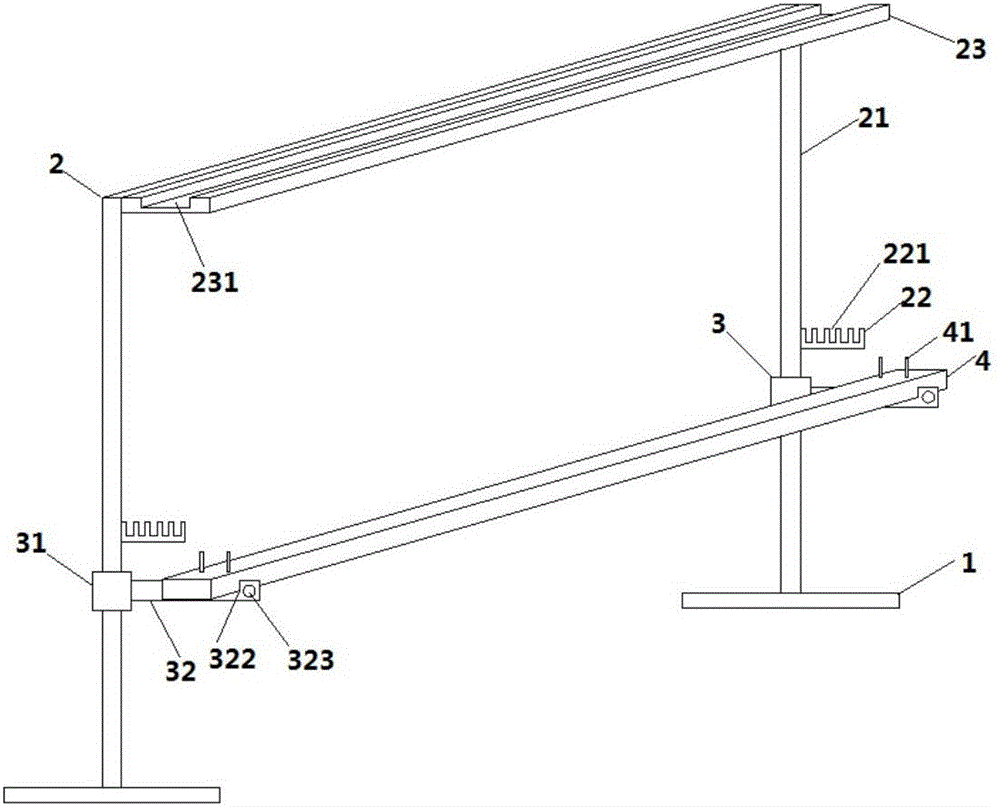
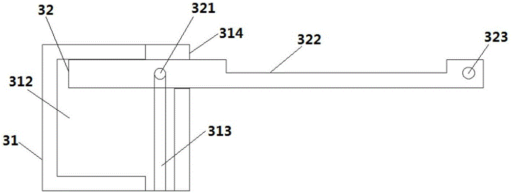
[0014] A reed rack, such as figure 1 As shown, it includes a leg 1 and a bracket 2. The uprights 21 on both sides of the bracket 2 are provided with a pole 22 perpendicular to the bracket 2, and the pole 22 is provided with a limiting groove 221 for clamping the heddle. The column 21 below the pole 22 is provided with a support bar 3 in the same direction as the pole 22, and a horizontal plate 4 is horizontally mounted on the support bar 3, and the horizontal plate 4 is provided with a limit pile 41, and the support bar 3 is fixed The seat 31 and the movable rod 32 are formed, the fixed seat 31 is fixed on the column 21, and the fixed seat 31 is provided with a slot 311 that runs through the fixed seat 31 in the vertical direction, and the fixed seat 31 is provided with the slot 311 Connected flat cavity 312, the two side walls of the slot 311 are provided with vertical grooves 313, the bottom of the groove 313 is in a through state, the movable rod 32 is a strip rod, and the ...


PUM


Abstract

The invention discloses a reeding frame which comprises support legs and a support. Stand columns arranged on the two sides of the support are each provided with a support bar perpendicular to the support, and each support bar is provided with limiting grooves used for clamping draft strips; the portion, under each support bar, of the corresponding stand column is provided with a supporting rod in the direction same as the support bar, and a transverse plate is transversely erected on the supporting rods and provided with limiting piles; each supporting rod is composed of a fixed seat and a movable rod, the fixed seats are fixed on the stand columns, each fixed seat is provided with an inserting groove penetrating through the fixed seat in the vertical direction, and the movable rods are inserted into the inserting grooves from bottom to top; limiting columns are clamped into grooves, the movable rods are rotated by taking the limiting columns as shafts, the tail ends of the movable rods abut against the upper tops of cavities, the movable rods located at the other sides of the limiting columns are erected on side openings, and the movable rods are horizontally arranged. According to the reeding frame, the structure is simple, use is convenient, a reeding stool is perfectly replaced with the supporting rods and the transverse plate, the reeding frame can be freely disassembled and arranged in a hidden mode, and the land occupation space of a drafting and reeding frame is reduced, so that a field is tidier.

Description

technical field [0001] The invention relates to the field of textile equipment, in particular to a reed rack. Background technique [0002] Heald reeding is an important front-end production process of fabric weaving, and the efficiency of heald drawing and reeding directly affects the level of weaving efficiency. The existing heald threading and reeding device is mainly composed of a weaving beam support and a heald support. Then put the warp yarn on the weaving beam on the heddle according to the design requirements, and finally pass the warp yarn through the steel reed through the reed. During the traditional reed operation, the reed is placed on the reed bench. The traditional reed bench not only takes up a lot of space, but also affects the passability and cleanliness of the site when the reed operation is not performed. Contents of the invention [0003] The technical problem to be solved by the present invention is to overcome the defects of the prior art, provide...

Claims


Application Information

Patent Timeline
Patent Type & Authority Applications(China)
IPC IPC(8): D03J1/14
CPCD03J1/14
Inventor 汪池
Owner 安徽江南明泽纺织有限公司
Why Eureka
Try Eureka