
Manually-assembled foundation

A prefabricated and basic technology, applied in infrastructure engineering, construction, etc., can solve the problems of inconvenient movement, inability to disassemble the base plate, waste of cost, etc., and achieve the effect of enhancing shear resistance, increasing weight, and avoiding relative torsion.

Active Publication Date: 2016-11-09
ZHEJIANG HEQIN COMM ENG
View PDF7 Cites 2 Cited by
  • Summary
  • Abstract
  • Description
  • Claims
  • Application Information

AI Technical Summary

Problems solved by technology

The foundation floor in this patent is integrally formed with concrete. When the iron tower needs to be replaced, the foundation floor cannot be disassembled and is inconvenient to move. It can only be discarded, which is a waste of cost.

Method used


Image

  • Manually-assembled foundation
  • Manually-assembled foundation
  • Manually-assembled foundation

Examples


Embodiment 1

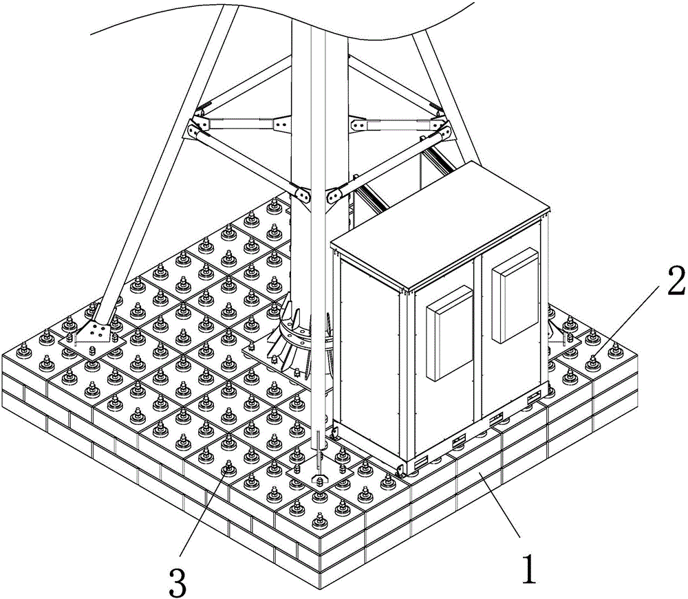
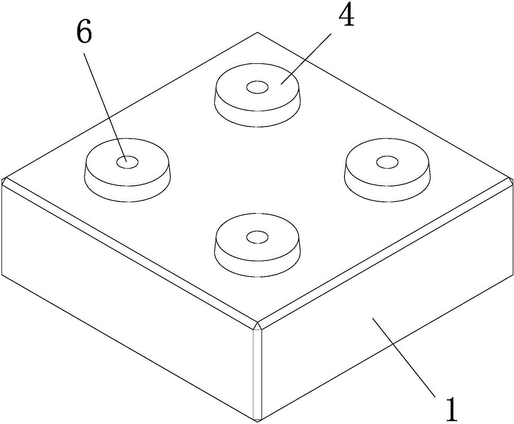
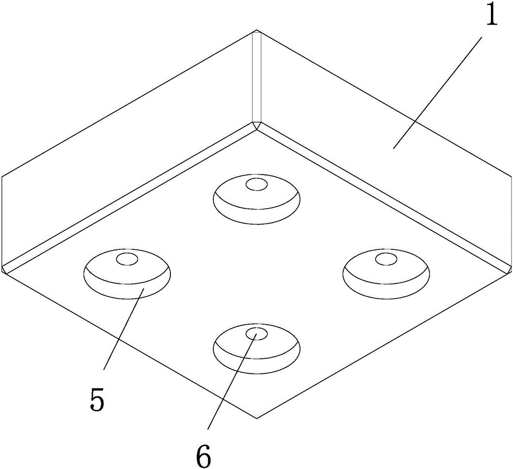
[0023] Embodiment 1: as figure 1 , 2 As shown in , 3, a kind of artificial assembly type foundation, comprises basic unit block 1, and basic unit block is square, and the upper surface corner of basic unit block is provided with positioning projection 4, and the lower surface of basic unit block is provided with another The positioning protrusion of a basic unit block matches the positioning pit 5, and the positioning protrusion runs through the basic unit block to be provided with a positioning hole 6, the positioning hole runs through a positioning rod 2, and the upper end of the positioning rod is provided with a lock nut 3. Such as Figure 4 As shown, the distance between the axes of the two positioning protrusions is twice the distance from the axis of the positioning protrusions to the two adjacent sides of the basic unit, and the positions of two adjacent basic unit blocks up and down are staggered.

[0024]The basic unit block is made of pre-cast concrete, and the ba...

Embodiment 2

[0025] Embodiment 2: The structure of this embodiment is basically the same as that of Embodiment 1, the difference is that, as Figure 5 , 6 As shown, two adjacent sides of the basic unit block are provided with limiting protrusions 7, and the other two adjacent sides are provided with limiting protrusions corresponding to the limiting protrusions of another basic unit block of the same structure. Matching limit groove 8. The basic unit block is provided with a fixing hole 9, and a wooden positioning sleeve 10 is arranged in the fixing hole. The height of the wooden positioning sleeve is the same as the thickness of the basic unit block, and the upper end of the wooden positioning sleeve protrudes from the surface of the basic unit block to form a positioning protrusion. The positioning hole is located at the axis of the wooden positioning sleeve. A pressure relief spring 11 is arranged between any adjacent two wooden positioning sleeves, such as Figure 8 As shown, the tw...


PUM


Abstract

The invention relates to a communication base station, in particular to a manually-assembled foundation. The manually-assembled foundation comprises foundation unit blocks, the foundation unit blocks are square, locating protrusions are arranged at the corners of the upper surface of each foundation unit block, locating pits matched with the locating protrusions of another foundation unit block are arranged on the lower surface of each foundation unit block, locating holes penetrating through the foundation unit blocks are formed in the locating protrusions, locating rods penetrate through the locating holes, and locking nuts are arranged at the upper ends of the locating rods. The manually-assembled foundation has the beneficial effects that disassembly can be realized, the position of a tower foundation is convenient to change, and the utilization rate of the tower foundation can be effectively increased.

Description

technical field [0001] The invention relates to a communication base station, in particular to an artificially assembled foundation. Background technique [0002] When erecting the communication tower and the computer room, it is necessary to build a tower foundation under the tower body or the computer room, and fix the communication tower and the computer room on the tower foundation. The existing type of tower foundation is usually cast on-site with concrete as a whole and cannot be disassembled. When the communication tower body and the machine room need to be replaced, the poured tower foundation can only be discarded in place and cannot be moved to replace the position. Disassembly and movement, waste of cost, and long construction period; there is another type of tower base that is detachable, but the ground needs to be excavated to bury the tower base underground, which is not conducive to repeated use and random combination into tower bases of different sizes, and ...

Claims


Application Information

Patent Timeline
Patent Type & Authority Applications(China)
IPC IPC(8): E02D27/42
CPCE02D27/42
Inventor 虞德群杨哲陈子平商宵旦姜志毅
Owner ZHEJIANG HEQIN COMM ENG
Learn More