
Air energy storage efficient energy recovery mechanism

An air energy storage and air compressor technology, applied in the field of energy storage, can solve the problems of low conversion rate, low recovery and utilization rate of excess electric energy, waste of electric energy, etc., and achieve high recovery and reuse rate, which is conducive to normal use.

Active Publication Date: 2018-04-06
零碳未来(重庆)能源发展有限公司
View PDF6 Cites 0 Cited by
  • Summary
  • Abstract
  • Description
  • Claims
  • Application Information

AI Technical Summary

Problems solved by technology

[0003] Existing solar generators include excess electric energy, air compressors, gas storage tanks and gas turbine generators. The air compressed by the air compressors is stored in the gas storage tanks. To generate electricity, high-pressure air is released from the gas storage tanks The gas generates electricity for the gas turbine generator. Since the air stored in the gas storage tank can only benefit the energy of its high-pressure gas part, the energy of its lower-pressure part is wasted, so there is little conversion of gas into electric energy, and the conversion rate is low. At the same time, the gas turbine generator can only use the energy of its high-pressure gas part, and the energy of its lower-pressure part is also wasted, resulting in a low recycling rate of excess electric energy and a large amount of waste of electric energy. The use of air compressors requires that the air should have low relative humidity, less dust, clean air and good ventilation, away from flammable, explosive, corrosive chemicals and harmful and unsafe items, and avoid places that emit dust. Under certain conditions, it will also affect the normal use of the air compressor

Method used


Image

  • Air energy storage efficient energy recovery mechanism
  • Air energy storage efficient energy recovery mechanism

Examples


Embodiment Construction

[0018] Below in conjunction with accompanying drawing and embodiment the present invention will be further described:

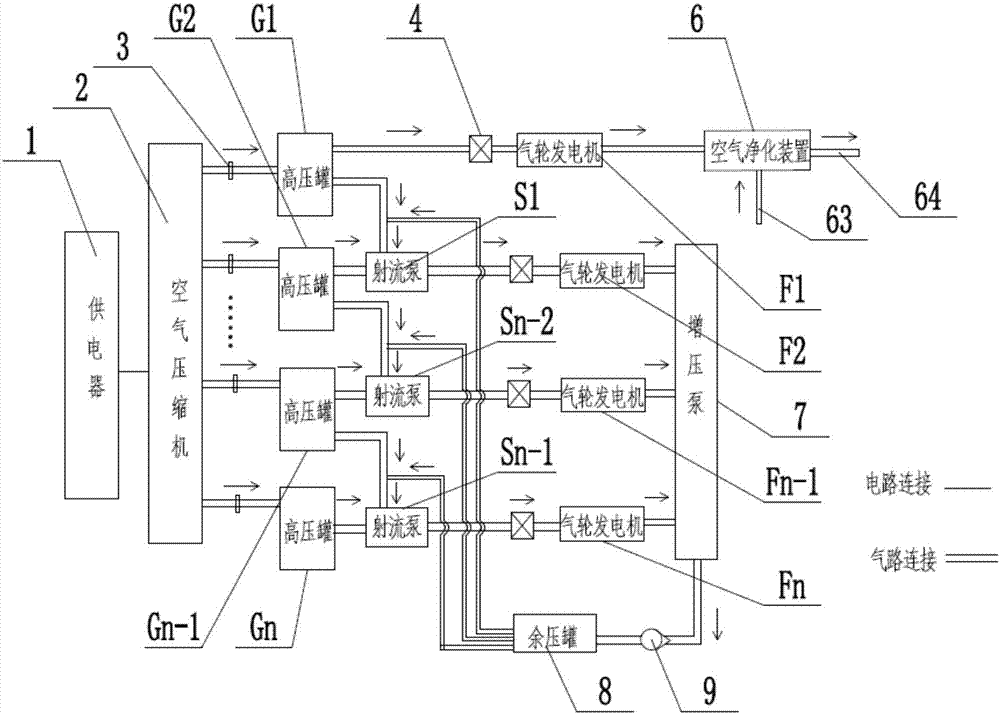
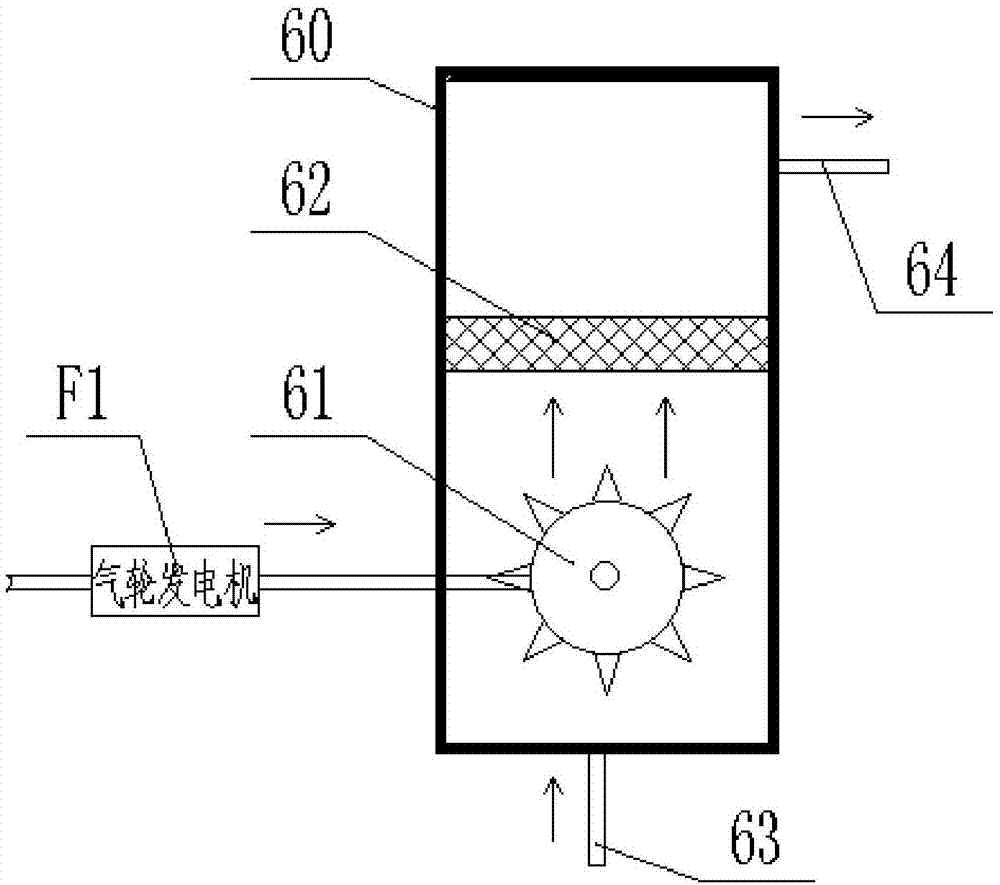
[0019] Such as figure 1 , 2 As shown, an air energy storage and high-efficiency energy recovery mechanism includes a power supply 1 that can provide green electric energy periodically, an air compressor 2, n high-pressure tanks (G1, G2...Gn-1, Gn), n-1 A jet pump (S1...Sn-2, Sn-1), n ​​turbine generators (F1, F2...Fn-1, Fn), an air purification device 6, a booster pump 7 and a residual pressure tank 8, Where n is a positive integer greater than 1.

[0020] The output terminal of the power supply 1 is connected to the input terminal circuit of the air compressor 2. The power supply 1 increases the electric energy for the air compressor 2 and drives it to work. When the air compressor 2 works, the low-pressure gas will be Convert into high-pressure gas, this gas can specifically be air, there are n output ends on the described air compressor 2, and each outp...


PUM


Abstract

The invention discloses an air energy storage and high-efficiency energy recovery mechanism, which includes a power supply, an air compressor, n high-pressure tanks, n-1 jet pumps, n gas turbine generators, an air purification device, a booster pump and other components. Pressure tank, the power supply is connected to the air compressor, and the air compressor is connected to the input ends of n high-pressure tanks; the first high-pressure tank high-pressure output gas path is equipped with a first gas turbine generator, and the first gas turbine generator is connected to the air purification device ; The remaining n-1 high-pressure tank high-pressure output ends are respectively connected to the first input ends of n-1 jet pumps in one-to-one correspondence, and the n-1 jet pump high-pressure output gas circuits are respectively equipped with gas turbine generators, n-1 The gas path downstream of the gas turbine generator converges to the input end of the booster pump, the output end of the booster pump is connected to the input end of the residual pressure tank, and the output end of the residual pressure tank is respectively connected to the second input ends of n-1 jet pumps; the present invention can Purify the air environment and improve the recovery and reuse rate of electric energy.

Description

technical field [0001] The invention belongs to the technical field of energy storage, and in particular relates to an air energy storage and high-efficiency energy recovery mechanism. Background technique [0002] The unbalanced power load in the world is becoming increasingly prominent, and the peak-to-valley difference of the power grid is gradually widening. At the same time, people have higher and higher requirements for the power supply quality of the power grid. It is matched to alleviate the situation that the peak-to-valley difference of the system load is too large. Electric energy storage system is also an effective means to improve the utilization rate of renewable energy such as wind power and solar power. In addition, the power energy storage system is also a key technology to solve the problems of small capacity and large load fluctuation of distributed energy systems. [0003] Existing solar generators include excess electric energy, air compressors, gas st...

Claims


Application Information

Patent Timeline
Patent Type & Authority Patents(China)
IPC IPC(8): F04B35/04F04F5/54F01D15/10F01K25/08F01K17/04B01D46/00
CPCF01D15/10F01K17/04F01K25/08F04B35/04F04F5/54B01D46/62
Inventor 刘琪李均
Owner 零碳未来(重庆)能源发展有限公司
Learn More