Locking device and application thereof

A locking device and locking seat technology, applied in the connection of rods, connecting components, stone processing tools, etc., can solve the problems of easy damage to the saw blade body, low accuracy, poor flatness of the plate, etc., to improve stability and reliability. Accuracy, ensure stable operation, improve the effect of stability

Active Publication Date: 2016-11-09
QUANZHOU HAIENDE ELECTROMECHANICAL TECH DEV
View PDF4 Cites 2 Cited by
  • Summary
  • Abstract
  • Description
  • Claims
  • Application Information

AI Technical Summary

Problems solved by technology

However, in a high-load and high-vibration environment, wear and tear will inevitably occur between the sliding column and the column sleeve on the machine body, resulting in a gap on the mating surface. The gap will gradually expand with the increase in the use of the machine. It will also shake with the lifting column, and the irregular additional force generated by this shaking will act on the saw blade, which will not only cause poor flatness and low precision of the processed plate, which will seriously affect the processing quality, but also make the saw The chip and the body are easily damaged, which affects the service life of the equipment and the maintenance cost of the equipment is high

Method used


Image

  • Locking device and application thereof
  • Locking device and application thereof
  • Locking device and application thereof

Examples


Embodiment Construction

[0044] The present case will be described in further detail below in conjunction with the accompanying drawings and specific embodiments.

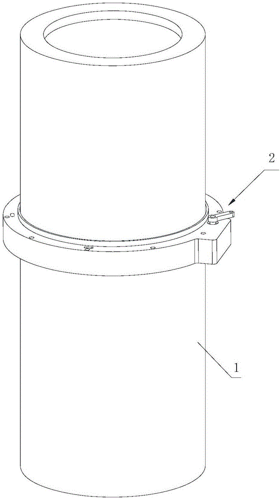
[0045] This case concerns a locking device, suitably installed at the corresponding movable part of the relevant equipment, such as figure 1 A schematic diagram is given, which is installed on the lifting column 1.

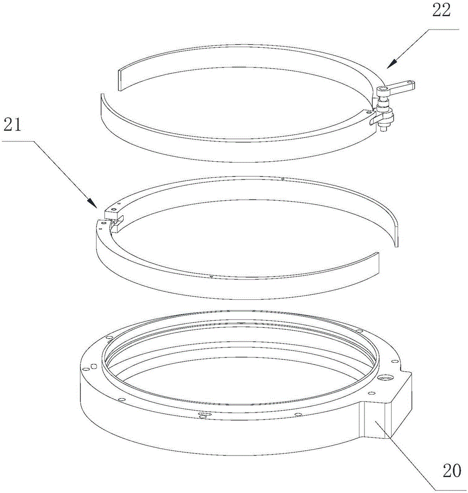
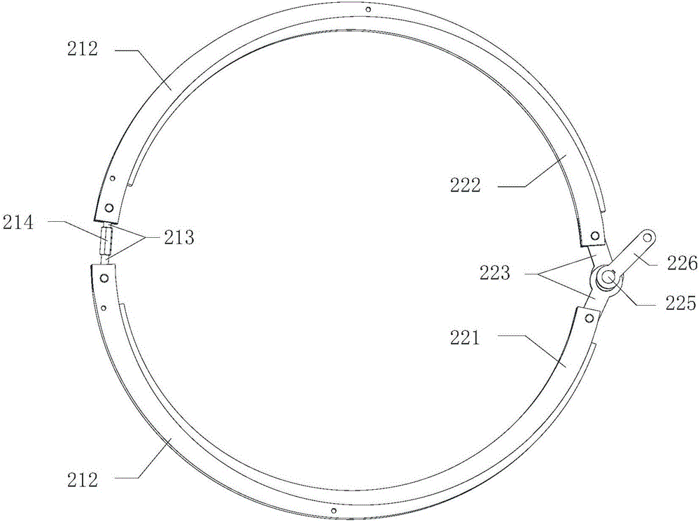
[0046] Such as Figure 2-11 As shown, the locking device 2 includes a locking seat 20 , an outer locking brake 21 and an inner locking brake 22 . The outer holding brake 21 is assembled in the locking seat 20, and the inner holding brake 22 is assembled in the inner side of the outer holding brake 21, and the two are matched and arranged. Specifically, the relevant parts have fixed parts and movable parts that are properly assembled with each other, such as a crossbeam as a fixed part, and a lifting column 1 that runs through the crossbeam as a movable part for lifting activities, and the locking seat 20 is fixedly installed...


PUM


Abstract

The invention discloses a locking device and an application thereof. The locking device comprises a locking base, an outer brake and an inner brake, wherein the outer brake is assembled in the locking base, and the inner brake is assembled on the inner side of the outer brake; the inner brake comprises a semi-circular left inner brake and a semi-circular right inner brake and further comprises an inner adjustment mechanism for adjusting the left inner brake and the right inner brake which are matched for locking adjustment. The locking device can be applied to various mechanical equipment and specifically mounted on a corresponding movable part of a related device properly, and the inner brake embraces the movable part; accordingly, the stability and the precision of the movable part are improved during moving, shaking of the movable part in high-load and high-vibration environments is avoided, the stability and the precision of the device are improved, and the service life of the device is prolonged.

Description

technical field [0001] The invention relates to the technical field of mechanical equipment, in particular to a locking device and its application. Background technique [0002] In various fields of mechanical equipment, it is very common to achieve related operations through multi-dimensional movements, and the stability and accuracy during the movement are very critical. For example, the existing stone cutting machine is designed with a vertical lifting operation. The lifting column is slidably matched with the column sleeve on the body, and a wear-resistant sleeve is embedded in the column sleeve of the body, such as a copper sleeve or a self-lubricating bearing. Take necessary dust-proof measures to minimize the infiltration of dust. However, in a high-load and high-vibration environment, wear and tear will inevitably occur between the sliding column and the column sleeve on the machine body, resulting in a gap on the mating surface. The gap will gradually expand with t...

Claims


Application Information

Patent Timeline
Patent Type & Authority Applications(China)
IPC IPC(8): F16B7/04F16B7/18
CPCB28D1/02B28D7/00F16B7/0406F16B7/182
Inventor 林智敏华新陆吴江文
Owner QUANZHOU HAIENDE ELECTROMECHANICAL TECH DEV
Why Eureka
Try Eureka