
A rotating shaft type binocular ranging telescope

A telescope and binocular technology, applied in the field of telescopes, can solve the problems of production, manufacturing and consumption restrictions, unsuitable for mass production, and high manufacturing cost, and achieves reduction of production difficulty and production cost, ease of mass production operations, and reliable laser light. The effect of ranging

Active Publication Date: 2019-01-11
南阳市诚辉光电有限责任公司
View PDF5 Cites 0 Cited by
  • Summary
  • Abstract
  • Description
  • Claims
  • Application Information

AI Technical Summary

Problems solved by technology

The development of binocular ranging telescopes is only produced and manufactured in a few countries such as the United States and Japan in developed countries. Very limited, the current penetration rate is extremely low, and the market selling price is above 1000$
Not only requires high precision of structural parts, but also requires extremely high precision of matching between optical glass and structural parts. Its structural method is not suitable for mass production at all, and the cost is too high to be accepted by the public.

Method used


Image

  • A rotating shaft type binocular ranging telescope
  • A rotating shaft type binocular ranging telescope
  • A rotating shaft type binocular ranging telescope

Examples


Embodiment 1

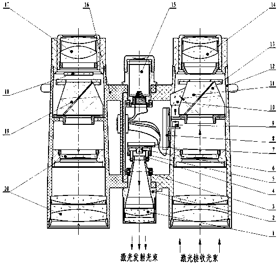
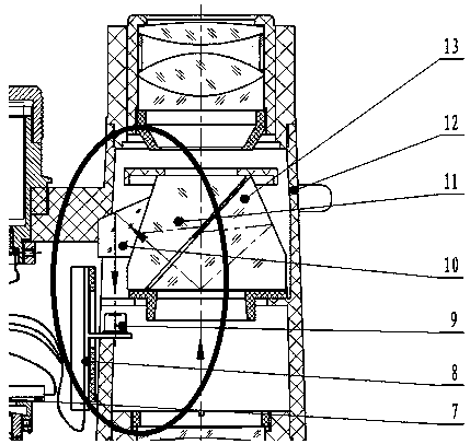
[0029] see figure 1 , 2 Shown: the shaft-type binocular ranging telescope of the present invention includes left and right lens barrels and a central axis. The central axis is provided with a laser emitting mechanism, one of the lens barrels is provided with a laser receiving mechanism, and the other lens barrel is provided with a There is a distance measurement result display mechanism, and the laser emitting mechanism is rigidly connected with the lens barrel provided with the laser receiving mechanism, such as figure 1 As shown, the left lens barrel is provided with a laser receiving mechanism, and the right lens barrel is provided with a distance measurement result display mechanism.

[0030] The laser emitting mechanism includes an emitting lens barrel 2 fixed with an emitting objective lens 1 at the front end, and the emitting lens barrel 2 is rigidly connected with the left lens barrel 12. The circuit board 7 is connected, and the front and rear adjustment mechanism i...

Embodiment 2

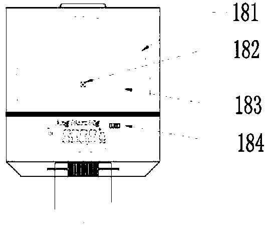
[0035] see Figure 4 The difference between this embodiment and Embodiment 1 is that the LCD display reticle 18 is a backlight LCD reticle, including a reticle glass 18-2, and its lower part is a backlight LCD panel 18-1, which is provided with The diffuse reflection background 18-3 of the backlight source 18-4 illuminates the backlight LCD panel 18-1, effectively realizing the reading of distance measurement data at night.

Embodiment 3

[0037] Such as Figure 5 As shown, the difference between this embodiment and Embodiments 1 and 2 is that the distance measurement result display mechanism is an OLED projection display mechanism, which includes an OLED display screen 21, a projection lens 22 and a relay prism arranged coaxially in sequence. 23. The glued surface of the relay prism 23 and the semi-pentaprism 19 is coated with a narrow-band light-passing film, and the OLED display 21 displays digitally the information fed back from the ranging board, and enters the semi-pentaprism through the projection lens 22 and the transfer prism 23 19 is imaged at the position of the focal plane 24 of the eyepiece, and the human eye observes through the eyepiece 17 .

[0038] When the present invention performs laser ranging, the ranging main board controls the laser diode 6 to send out laser light which is collimated by the transmitting objective lens 1 and shoots to the measured object, and the reflected laser light of t...


PUM


Abstract

The invention discloses a rotating-shaft type binocular ranging telescope, which includes left and right lens barrels and a central shaft, the central shaft is provided with a laser emitting mechanism, one of the lens barrels is provided with a laser receiving mechanism, and the laser emitting mechanism is connected with the The lens barrel provided with the laser receiving mechanism is rigidly connected. Without changing the basic shape of the telescope, it is effectively realized that during the process of adjusting the eye distance of the telescope, the relative displacement between the laser emitting mechanism and the lens barrel equipped with the laser receiving mechanism does not occur at all times, so that the optical system of the laser emitting mechanism and the laser receiving mechanism The optical axis does not change, and accurate laser distance measurement can be realized stably and reliably. The processing accuracy requirements of all parts are the same as those of traditional telescope products, which greatly reduces the production difficulty and production cost of the rotating shaft binocular ranging telescope, facilitates mass production operations, and is worthy of wide application.

Description

technical field [0001] The invention belongs to the technical field of telescopes, in particular to a rotating shaft type binocular ranging telescope. Background technique [0002] Laser ranging is an important application of modern technology in the field of measurement. It is widely used in many aspects of military and civilian use. Many fields such as distance measurement, speed measurement, angle measurement, and height measurement have demonstrated its high-speed, accurate, and convenient measurement advantages. It is a traditional Measurements are incomparable. With the development of science and technology and the continuous improvement of people's living standards, especially the progress of semiconductor lasers, the combination of ranging and civilian telescopes has become a popular telescopic system. [0003] At present, the civil technology of monocular ranging telescopes is relatively mature, and has formed large-scale production and application in the world. T...

Claims


Application Information

Patent Timeline
Patent Type & Authority Patents(China)
IPC IPC(8): G01C3/04
CPCG01C3/04
Inventor 许东升彭德辉盖晓华郭学军兰星明孙文秀
Owner 南阳市诚辉光电有限责任公司
Learn More