
A launcher for a surface surveillance radar system

A surface surveillance radar and transmitter technology, applied in the field of surface surveillance radar system transmitters, can solve the problems of messy cable connection, reduced heat transfer efficiency, microwave signal leakage, etc., to improve assembly and maintenance efficiency, reduce cable connections, structure The effect of high compactness

Active Publication Date: 2019-06-11
ANHUI SUN CREATE ELECTRONICS
View PDF6 Cites 0 Cited by
  • Summary
  • Abstract
  • Description
  • Claims
  • Application Information

AI Technical Summary

Problems solved by technology

In the above-mentioned field surveillance radar products, the transmitter structure as the signal transmitting element is very important. The current design defects of the above-mentioned transmitter structure are as follows: First, due to the large number of high-power components inside the structure, the current transmitter has many The fan cooling method not only leads to poor cooling effect, but also may increase thermal resistance, resulting in reduced heat transfer efficiency
Second, traditional transmitters mostly use cable connection to ensure the electrical connection and signal transmission between internal components, especially for the RF output part of the signal, which is very prone to leakage of microwave signals
At the same time, due to the messy cable connection methods between various components, it is necessary to have a very high resolution efficiency for each cable joint during early wiring and later maintenance wiring, which obviously brings additional troubles to wiring personnel
Third, due to the integrated structure of the shell and the panel of the traditional transmitter, and the panel is often equipped with fragile and vulnerable parts such as handles, operation buttons and even the socket of the launch assembly; Under the premise of the integrated structure with the panel, how to quickly replace the panel has become a difficult problem, which has brought great trouble to the actual maintenance personnel

Method used


Image

  • A launcher for a surface surveillance radar system
  • A launcher for a surface surveillance radar system
  • A launcher for a surface surveillance radar system

Examples


Embodiment Construction

[0027] For ease of understanding, here in conjunction with each accompanying drawing concrete structure of the present invention and course of work are further described as follows:

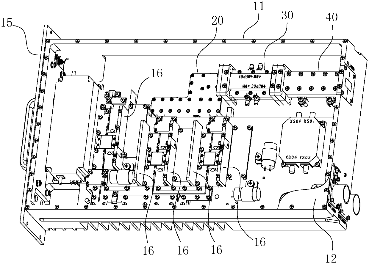
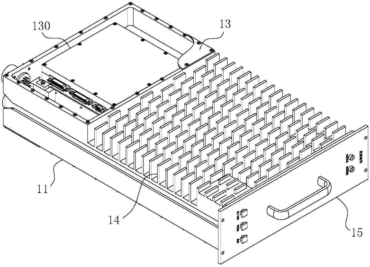
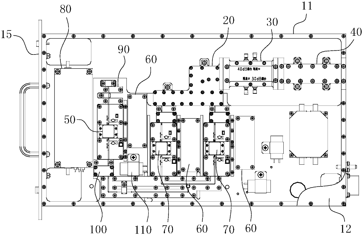
[0028] The specific structure of the present invention is as Figure 1-5 As shown, it includes a box-shaped housing 11, an upper cover plate 12 arranged at the box mouth of the housing 11 parallel to the bottom of the housing 11, and an upper cover plate 12 parallel to the lower cover plate 12 arranged at the back of the housing 11. cover plate 13. Specific as figure 1 and image 3 As shown, a set of main power amplifiers 80, five sets of transitional microstrip boards 90, three sets of power supply boards 60, a set of 50W power amplifiers 50, three sets of isolators 100, three sets of capacitors 110 are installed in the cavity of the housing 11. Two sets of 150W power amplifiers 70 and splitter microstrip board 120 , waveguide combiner 20 , coupler 30 and filter 40 . Such as figure 1 As sho...


PUM


Abstract

The invention belongs to the field of radar electronic communication, and particularly relates to a transmitting device of a scene surveillance radar system. The transmitting device comprises a box-shaped housing and an upper cover board for closing the box opening of the housing. The box chamber of the housing forms an accommodating chamber for accommodating components. The components at least comprise a waveguide synthesizer, a coupler and a filter, wherein the waveguide synthesizer, the coupler and the filter are successively arranged in an engaging manner. The adjacent matching surfaces of the waveguide synthesizer, the coupler and the filter are flange surfaces and form a fixed flange fit. A shielding sealing ring which is used for improving electromagnetic shielding capability is embedded into each flange surface. The transmitting device has advantages of improving assembling and maintenance efficiency of the device, and effectively reducing or even preventing leakage of microwave signals. The transmitting device has advantages of high structure compactness, smaller device size, and effective improvement of convenience in maintenance.

Description

technical field [0001] The invention belongs to the field of radar electronic communication, and in particular relates to a launcher for a surface surveillance radar system. Background technique [0002] Surface surveillance radars are generally installed on airport towers to monitor targets such as aircraft and vehicles within the near-ground range and extract information such as distance and azimuth of targets. They have the advantages of high positioning accuracy, fast data refresh rate, and high reliability. In the above-mentioned field surveillance radar products, the transmitter structure as the signal transmitting element is very important. The current design defects of the above-mentioned transmitter structure are as follows: First, due to the large number of high-power components inside the structure, the current transmitter has many The use of fan air cooling not only leads to poor cooling effect, but also may increase thermal resistance, resulting in reduced heat ...

Claims


Application Information

Patent Timeline
Patent Type & Authority Patents(China)
IPC IPC(8): G01S7/282G01S7/35G01S13/91G01S13/89
CPCG01S7/282G01S7/35G01S13/89G01S13/91
Inventor 王家明刘鲁军汤咏张荣斌董青吴良姜炎
Owner ANHUI SUN CREATE ELECTRONICS
Learn More