Electro-optic material lenticular lens array structure and display device comprising same

A technology of electro-optical materials and lenticular lenses, which is applied in the direction of lenses, optics, optical components, etc., can solve the problems of easy bending and deformation of the second substrate, and achieve the effect of avoiding bending deformation and good 3D display effect

Active Publication Date: 2018-01-09
ZHANGJIAGANG KANGDE XIN OPTRONICS MATERIAL
View PDF7 Cites 0 Cited by
  • Summary
  • Abstract
  • Description
  • Claims
  • Application Information

AI Technical Summary

Problems solved by technology

[0008] The main purpose of the present application is to provide an electro-optic material lenticular lens array structure and a display device including it, so as to solve the problem that the second substrate is easily bent and deformed in the prior art

Method used


Image

  • Electro-optic material lenticular lens array structure and display device comprising same
  • Electro-optic material lenticular lens array structure and display device comprising same
  • Electro-optic material lenticular lens array structure and display device comprising same

Examples


Embodiment Construction

[0054] It should be pointed out that the following detailed description is exemplary and intended to provide further explanation to the present application. Unless defined otherwise, all technical and scientific terms used herein have the same meaning as commonly understood by one of ordinary skill in the art to which this application belongs.

[0055] It should be noted that the terminology used here is only for describing specific implementations, and is not intended to limit the exemplary implementations according to the present application. As used herein, unless the context clearly dictates otherwise, the singular is intended to include the plural, and it should also be understood that when the terms "comprising" and / or "comprising" are used in this specification, they mean There are features, steps, operations, means, components and / or combinations thereof.

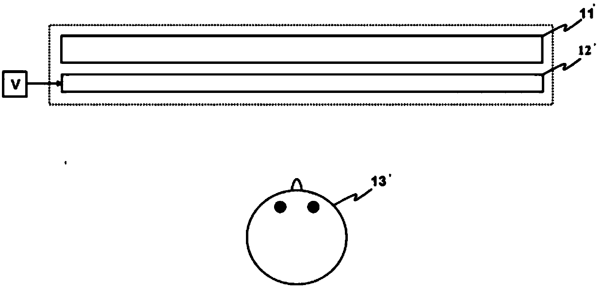
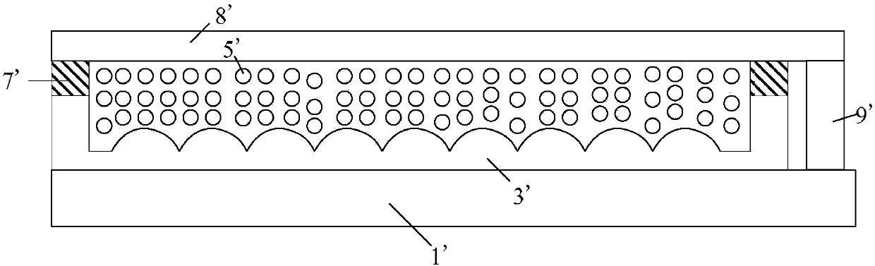
[0056] As introduced in the background art, in the existing electro-optic material lenticular lens array structu...


PUM

PropertyMeasurementUnit
heightaaaaaaaaaa

Abstract

The application provides an electrooptical material columnar lens array structure and a display device including the same. The electrooptical material columnar lens array structure comprises a first substrate, a second substrate, a planoconvex lens assembly, a sealing part and a plurality of electro-optical material molecules. The first substrate comprises a first electrode layer. The second substrate includes a second electrode layer, and a gap is arranged between the second electrode layer and the first electrode layer. The plano-convex lens assembly is arranged in the gap, and includes a convex lens array composed of a plurality of convex lenses each having a convex surface. At least one convex surface is provided with at least one protruding portion protruding toward the second electrode layer. The sealing part is provided in the gap, and the second electrode layer, the planoconvex lens assembly and the sealing part form a sealed space, or the first electrode layer, the second electrode layer and the sealing part form a sealed space. The electro-optical material molecules are arranged in the sealed space. The electrooptical material columnar lens array structure alleviates the problem that the second substrate is easily bent and deformed.

Description

technical field [0001] The present application relates to the field of 2D / 3D switchable display, in particular, to an electro-optical material lenticular lens array structure and a display device including the same. Background technique [0002] Such as figure 1 What is shown is a schematic diagram of a known display device for switching between 2D and 3D images. For known 2D and 3D image switchable display devices (2D and 3D Image Switchable Display), generally a liquid crystal view separation component 12' (Liquide Crystal View Separator) is installed in front of the screen of the liquid crystal display 11'. For the viewing position of the viewer 13', the installation method of installing the liquid crystal view separation assembly 12' in front of the screen of the liquid crystal display 11' is called a front installation method (Front Installation Method). [0003] In addition, driven by an appropriate external electrical voltage V, the liquid crystal view separation co...

Claims


Application Information

Patent Timeline
Patent Type & Authority Patents(China)
IPC IPC(8): G02B3/00G02B27/22G02F1/1343G02F1/29
CPCG02B3/0006G02B3/0037G02B30/27G02F1/134309G02F1/29
Inventor 林明彦张晶范延江曾凡初刘甫潭
Owner ZHANGJIAGANG KANGDE XIN OPTRONICS MATERIAL
Why Eureka
Try Eureka