
Whirl flutter analysis method of propeller-driven aircraft

A flutter analysis and propeller technology, applied in special data processing applications, instruments, electrical digital data processing, etc., can solve problems such as the lack of spiral flutter analysis methods, the inability of NASTRAN to perform time domain simulation, and the inconvenience of propeller load transfer

Inactive Publication Date: 2016-11-09
XIAN AIRCRAFT DESIGN INST OF AVIATION IND OF CHINA
View PDF3 Cites 14 Cited by
  • Summary
  • Abstract
  • Description
  • Claims
  • Application Information

AI Technical Summary

Problems solved by technology

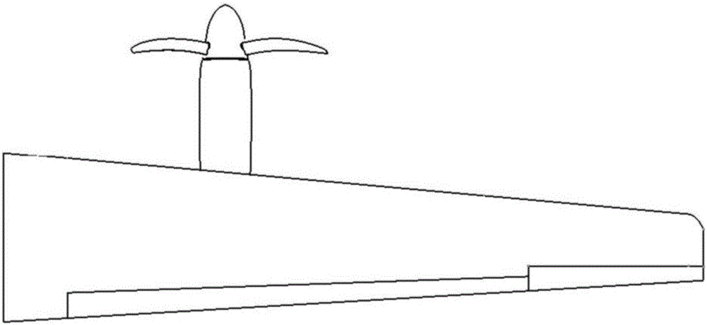
[0002] The structural relationship of propeller aircraft wing / nacelle / propeller is as follows: figure 1 As shown, foreign countries conduct spiral flutter analysis based on NASTRAN software, which imports propeller aerodynamic force into NASTRAN in the form of aerodynamic stiffness and damping matrix through DMAP language for flutter frequency domain analysis, but users are inconvenient for the load transfer between propellers Write out, while using NASTRAN can not perform time domain simulation
Domestic research on propeller flutter focuses on two-degree-of-freedom propeller stability analysis and four-degree-of-freedom propeller / wing stability analysis considering wing ups and downs and pitching degrees of freedom. There is no effective propeller flutter suitable for engineering model applications. vibration analysis method

Method used


Image

  • Whirl flutter analysis method of propeller-driven aircraft
  • Whirl flutter analysis method of propeller-driven aircraft
  • Whirl flutter analysis method of propeller-driven aircraft

Examples


Embodiment Construction

[0021] In order to make the objectives, technical solutions and advantages of the present invention clearer, the technical solutions in the embodiments of the present invention will be described in more detail below in conjunction with the drawings in the embodiments of the present invention. In the drawings, the same or similar reference numerals denote the same or similar elements or elements having the same or similar functions throughout. The described embodiments are some, but not all, embodiments of the invention. The embodiments described below by referring to the figures are exemplary and are intended to explain the present invention and should not be construed as limiting the present invention. Based on the embodiments of the present invention, all other embodiments obtained by persons of ordinary skill in the art without making creative efforts belong to the protection scope of the present invention. Embodiments of the present invention will be described in detail b...


PUM


Abstract

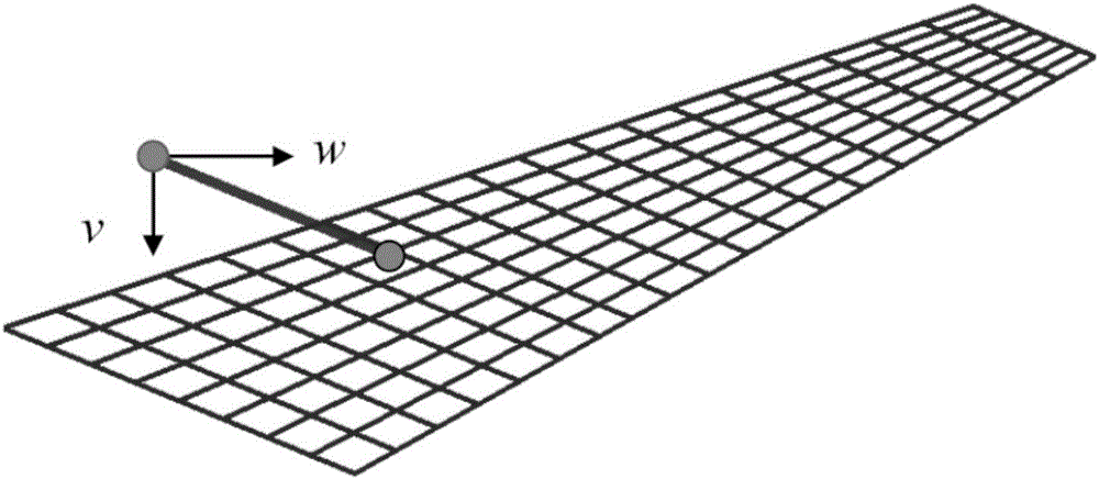
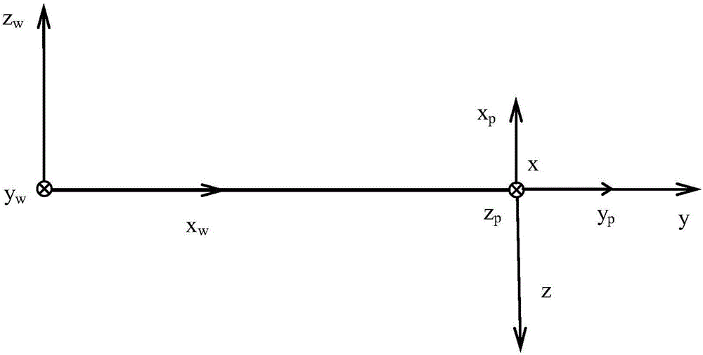
The invention relates to a whirl flutter analysis method of a propeller-driven aircraft. The whirl flutter analysis method comprises the following steps: 1) establishing a wing finite element model, and carrying out dynamic characteristic analysis; 2) calculating the dynamic characteristic of a nacelle / propeller system; 3) calculating an unsteady aerodynamic force influence coefficient matrix among wing aerodynamic grids and the aerodynamic influence coefficient matrix, on the sidewash w and the downwash v of a propeller hub point, of the wing aerodynamic grid; 4) calculating the aerodynamic derivatives of the propeller under different flight states, and assembling an aerodynamic matrix; 5) on the basis of an installation relationship of the wing / the nacelle / the propeller, deducing the mathematical expression form of the effective pitch angle and yaw angle of the propeller; 6) obtaining an unsteady aerodynamic force matrix which is applied to a wing installation point by the propeller to obtain a whirl flutter kinematic equation; and 7) solving the whirl flutter kinematic equation, and analyzing whirl flutter characteristics. The whirl flutter analysis method of the propeller-driven aircraft has the advantages of being high in analysis accuracy, wide in application ranges and the like.

Description

technical field [0001] The invention belongs to the field of aeroelastic design, in particular to a method for analyzing spiral flutter of a propeller aircraft. Background technique [0002] The structural relationship of propeller aircraft wing / nacelle / propeller is as follows: figure 1 As shown, foreign countries conduct spiral flutter analysis based on NASTRAN software, which imports propeller aerodynamic force into NASTRAN in the form of aerodynamic stiffness and damping matrix through DMAP language for flutter frequency domain analysis, but users are inconvenient for the load transfer between propellers Write out, while using NASTRAN can not perform time domain simulation. Domestic research on propeller flutter focuses on two-degree-of-freedom propeller stability analysis and four-degree-of-freedom propeller / wing stability analysis considering wing ups and downs and pitching degrees of freedom. There is no effective propeller flutter suitable for engineering model appli...

Claims


Application Information

Patent Timeline
IPC IPC(8): G06F17/50
CPCG06F30/23Y02T90/00
Inventor 杨佑绪黄国宁赵冬强唐矗程芳
Owner XIAN AIRCRAFT DESIGN INST OF AVIATION IND OF CHINA
Learn More