
Surgical robot system and surgical instrument position display method

A surgical robot and surgical instrument technology, applied in the field of medical devices, can solve the problems of affecting the operation speed, lack of overall sense, affecting the operation speed and operation efficiency, so as to improve the safety and success rate, and reduce the touch of fragile organs The probability of the operation, the effect of improving the operation speed and operation efficiency

Active Publication Date: 2017-08-18
SHANGHAI MICROPORT MEDBOT (GRP) CO LTD
View PDF5 Cites 23 Cited by
  • Summary
  • Abstract
  • Description
  • Claims
  • Application Information

AI Technical Summary

Problems solved by technology

[0008] At present, there are some defects in the use of surgical robots that are widely used clinically. For example, the field of view of the endoscope is small, which leads to a correspondingly small range that the doctor can see during operation, resulting in a decrease in operating comfort and operating speed. What's more serious is that when multiple surgical instruments are used for surgery at the same time, the doctor cannot see all the surgical instruments due to the narrow field of view of the endoscope, so that the doctor cannot clearly grasp the position of each surgical instrument during the operation. Lack of overall sense affects the operation speed and efficiency, and may even touch fragile organs in severe cases, which affects the safety of the operation and even causes the operation to fail
In particular, doctors often need to interrupt the operation and switch to endoscope control to move or enlarge the field of view of the endoscope to find surgical instruments that are not in the field of view, which seriously affects the operation speed

Method used


Image

  • Surgical robot system and surgical instrument position display method
  • Surgical robot system and surgical instrument position display method
  • Surgical robot system and surgical instrument position display method

Examples


Embodiment Construction

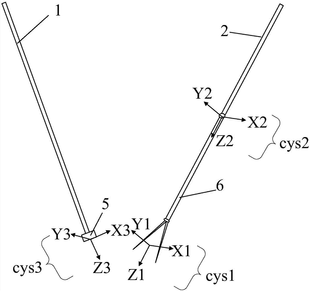
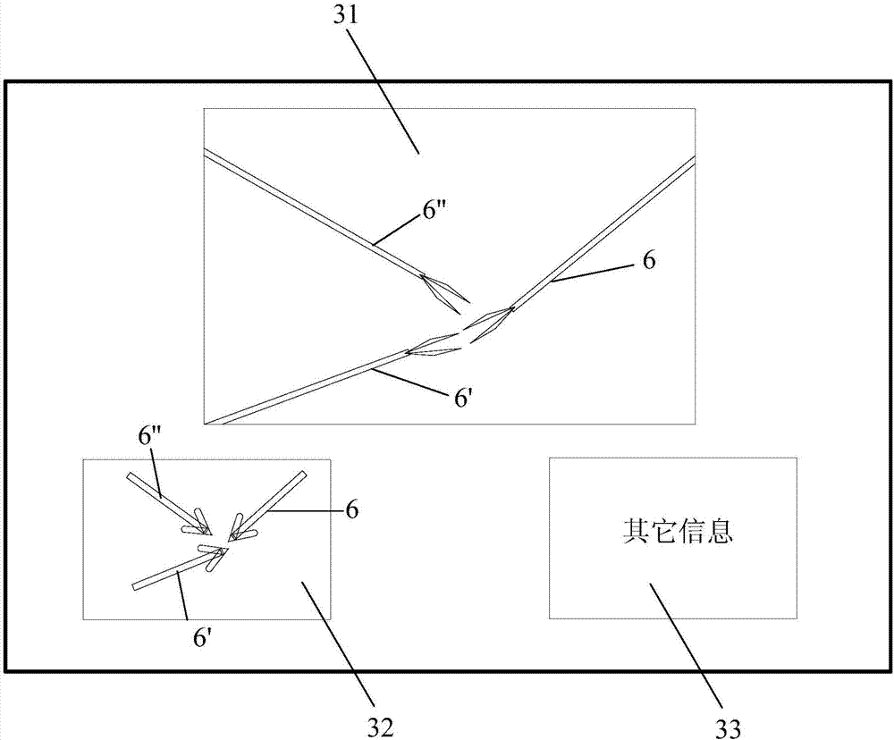
[0048] In order to make the purpose, advantages and features of the present invention clearer, the following is attached Figure 1~6 The surgical robot system and the method for displaying the position of surgical instruments proposed in the present invention will be described in further detail. It should be noted that the drawings are in a very simplified form and all use imprecise proportions, which are only used to conveniently and clearly assist in explaining the purpose of the embodiments of the present invention.

[0049] As in the description and claims, the "end" and "distal" refer to the end far away from the operator of the medical device, and the "proximal end" refers to the end close to the operator of the medical device

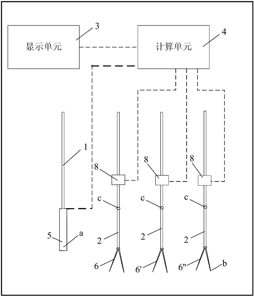
[0050] First, see figure 1 , Which is a structural block diagram of a surgical robot system provided by an embodiment of the present invention. The surgical robot system includes an image arm 1, a tool arm 2, a display unit 3 and a calculation unit 4...


PUM


Abstract

The invention relates to a surgical robot system and a surgical instrument position display method. The surgical robot system comprises an image arm, a tool arm, a display unit and a computing unit, wherein the image arm can be used for clamping an endoscope used for collecting image information; the tool arm is a fixed point mechanism and used for clamping a surgical instrument, and the surgical instrument comprises at least one feature point identifying surgical instrument position information; the display unit is connected with the computing unit in a communication mode, and an endoscope coordinate system is arranged at the tail end of the endoscope; the computing unit is used for obtaining coordinate values of the feature points under the endoscope coordinate system according to the forward kinematical equation, obtaining position information of the surgical instrument under the plane of an endoscope camera according to coordinate values and conducting imaging processing on the position information; the display unit receives the position information after imaging processing and displays the position information to improve surgical safety and efficiency.

Description

Technical field [0001] The present invention relates to the technical field of medical devices, in particular to a surgical robot system and a method for displaying the position of the surgical device. Background technique [0002] Since humans first applied robotic technology to brain surgery under CT navigation in the 1980s, surgical robotics technology has begun to develop and grow rapidly. At this stage, robotic surgery has been fully promoted. According to statistics, there are more than 520,000 robotic surgery performed annually worldwide. Among them, robotic minimally invasive surgery is the most important development direction of robotic surgery. In the field of urology in the United States, more than 50% of patients actively choose robotic minimally invasive surgery, and more than 90% of radical prostatectomy use minimally invasive surgical robots. carry out. Benefiting from the latest developments in many disciplines such as clinical medicine, robotics, mechanism, com...

Claims


Application Information

Patent Timeline
Patent Type & Authority Applications(China)
IPC IPC(8): A61B34/20A61B34/37
CPCA61B34/20A61B34/25A61B2090/061A61B2034/2059A61B2090/373A61B2090/365A61B90/37A61B2034/301A61B34/30A61B1/00149
Inventor 高旭师云雷何超王家寅朱祥姜逸之
Owner SHANGHAI MICROPORT MEDBOT (GRP) CO LTD
Learn More